Axle for a motor vehicle

Inactive Publication Date: 2014-05-22
ZF FRIEDRICHSHAFEN AG
View PDF2 Cites 6 Cited by
  • Summary
  • Abstract
  • Description
  • Claims
  • Application Information

AI Technical Summary

Benefits of technology

The patent aims to provide an axle for vehicles that can improve the damping of the axle and extend the life of the drive unit near the wheel.

Problems solved by technology

Owing to the arrangement of the drive unit close to the wheel on the vehicle axle, the drive unit is subjected to severe lifting and impact movements because of the jouncing motions of the electric vehicle wheel concerned.

Method used


Image

  • Axle for a motor vehicle
  • Axle for a motor vehicle
  • Axle for a motor vehicle

Examples


Embodiment Construction

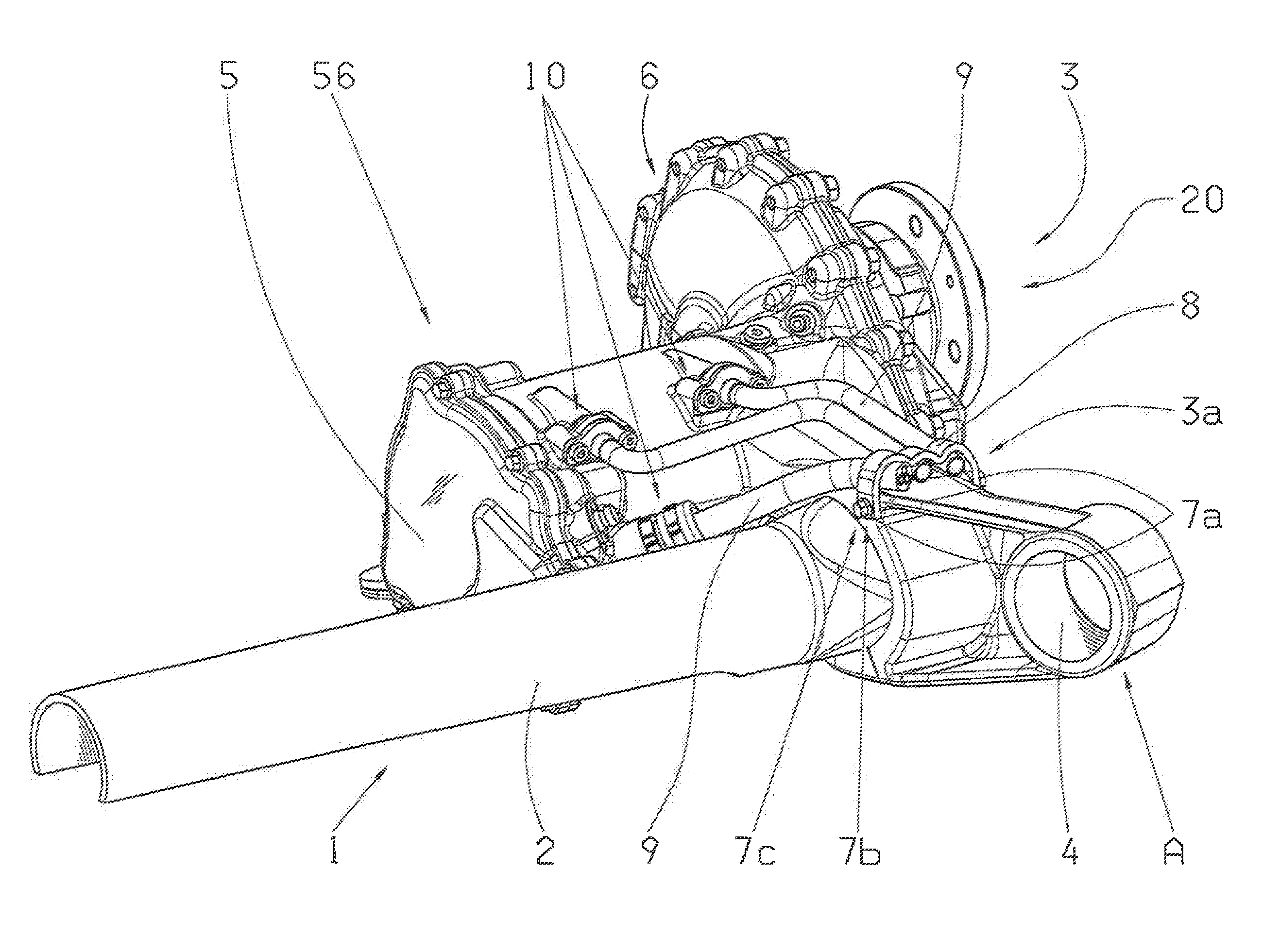
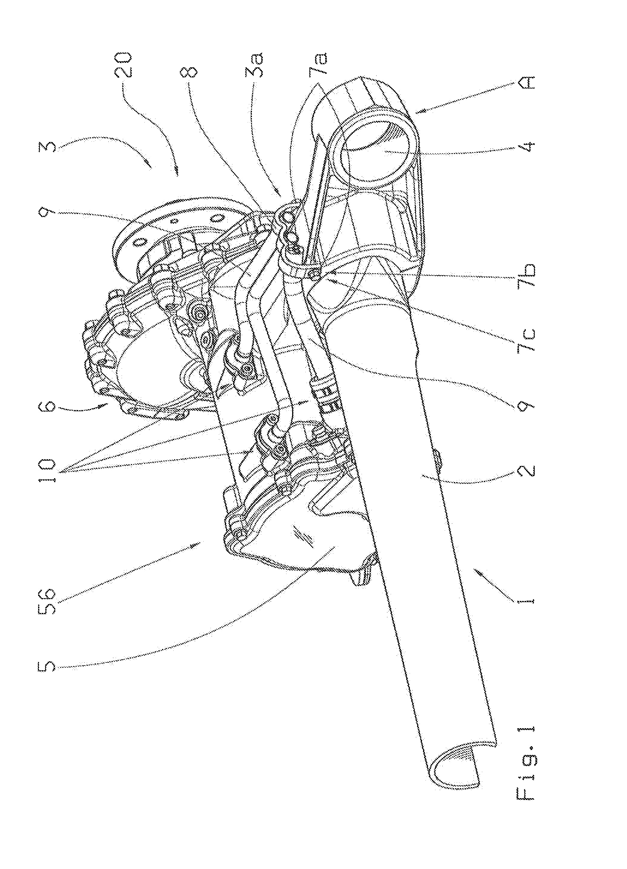
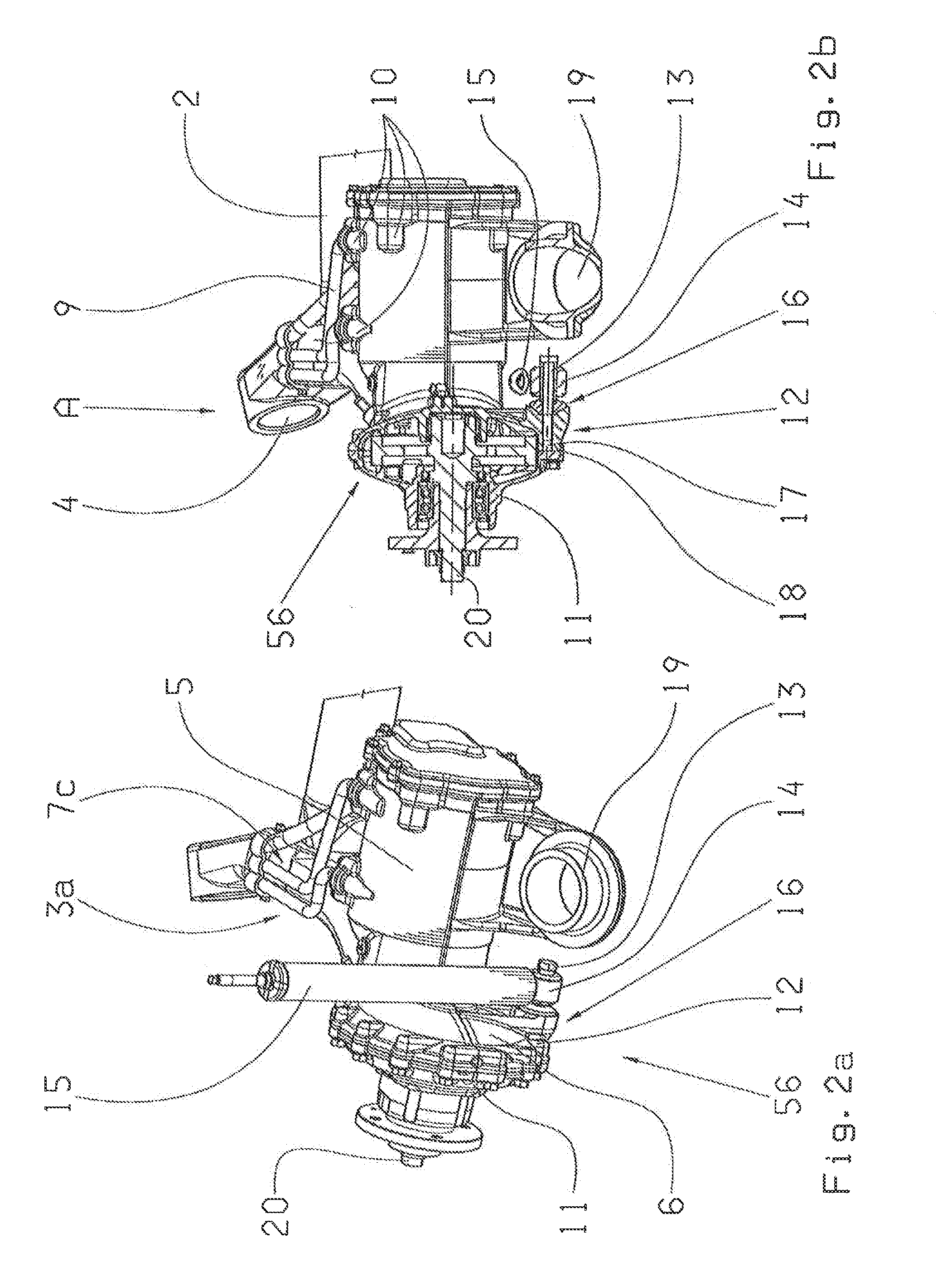
[0029]FIG. 1 shows a vehicle axle according to a first embodiment of the present invention, represented in three dimensions.

[0030]In FIG. 1 the index 1 denotes a torsion beam axle. The torsion beam axle 1 has a transverse profile 2 which in FIG. 1 extends essentially from lower left to upper right. On the right-hand side of the transverse profile 2 is arranged a trailing arm 3. In this case the trailing arm 3 can swivel about a pivot point A on a body of an electric vehicle. Not shown are dampers by virtue of which the torsion beam axle is damped. When the wheel undergoes a jouncing movement the trailing arm 3 pivots about the pivot point A. On the side opposite the fixing eye 4 is arranged a drive unit 56 close to the wheel, which is itself at least partially formed as the trailing arm 3. The drive unit 56 comprises an electric motor 5 and a transmission unit 6. The driveshaft of the electric motor 5 is connected to a wheel shaft 20 by way of the transmission unit 6. The wheel shaf...


PUM


Abstract

A vehicle axle, in particular a torsion beam axle for an electric vehicle, with at least one trailing arm on which is arranged a drive unit located close to a wheel, and the drive unit comprises an electric machine and a transmission unit. The drive unit, close to the wheel, has at least one supply line and at least one damper such that the drive unit, close to the wheel, is formed at least partially as a trailing arm and the damper is connected, on at least one side, to the drive unit at least in a single-shear manner and can be connected, on at least the other side, to a body of the electric vehicle. The at least one vehicle axle is utilized on a motor vehicle.

Description

[0001]This application is a National Stage completion of PCT / EP2012 / 062400 filed Jun. 27, 2012, which claims priority from German patent application serial no. 10 2011 080 037.9 filed Jul. 28, 2011.FIELD OF THE INVENTION[0002]The invention concerns a vehicle axle, in particular a torsion beam axle for an electric vehicle, comprising at least one trailing arm on which is arranged, close to a wheel, a drive unit with an electric machine and a transmission unit, such that the drive unit close to the wheel comprises at least one supply line, and with at least one damper. The invention also concerns a motor vehicle with at least one vehicle axle.BACKGROUND OF THE INVENTION[0003]Such vehicle axles are used in electric vehicles and serve both for the suspension of the electric vehicle wheels concerned and also to drive those wheels. The vehicle axle is supported inter alia by at least one damper on the vehicle body for damping the jouncing movement of the wheel or wheels of the axle. For t...

Claims


Application Information

Patent Timeline
IPC IPC(8): B60K7/00B60K1/00
CPCB60K1/00B60K7/0007B60G7/001B60G7/008B60G21/051B60B35/003B60G2200/422B60G2204/1244B60G2204/129B60G2204/201B60G2206/11B60G2206/20B60L3/0061B60L2220/44B60L2240/36B60L2270/145B60K2007/0038B60K2007/0061B60L50/52Y02T10/70
Inventor MAIR, ULRICHPOLLMEYER, STEPHANMUNSTER, MARTIN
Owner ZF FRIEDRICHSHAFEN AG
Why Eureka
Try Eureka