Retractable infill panel for high-lift device

a technology of infill panel and high-lift device, which is applied in the direction of aircraft indicators, aircraft accessories, fuselages, etc., can solve the problems of imposing aerodynamic penalties on aircraft, system and structure within the fixed wing structure to become exposed to risk, and lateral gap to progressively open between lateral edges

Active Publication Date: 2014-05-22
AIRBUS OPERATIONS LTD
View PDF6 Cites 4 Cited by
  • Summary
  • Abstract
  • Description
  • Claims
  • Application Information

AI Technical Summary

Benefits of technology

[0023]The high-lift device preferably has a partially deployed configuration between the stowed configuration and the deployed configuration, and the a retractable infill panel is preferably arranged to progressively extend from the retracted configuration to a partially extended config

Problems solved by technology

Deployment of such devices relative to the fixed structure causes a lateral gap to progressively open between a lateral edge of the high-lift device and the fixed structure.
Such gaps can cause systems and structure within the fixed wing structure to become exposed to

Method used


Image

  • Retractable infill panel for high-lift device
  • Retractable infill panel for high-lift device
  • Retractable infill panel for high-lift device

Examples


Embodiment Construction

)

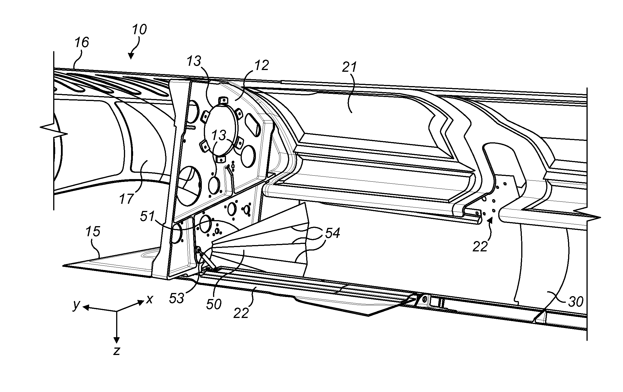
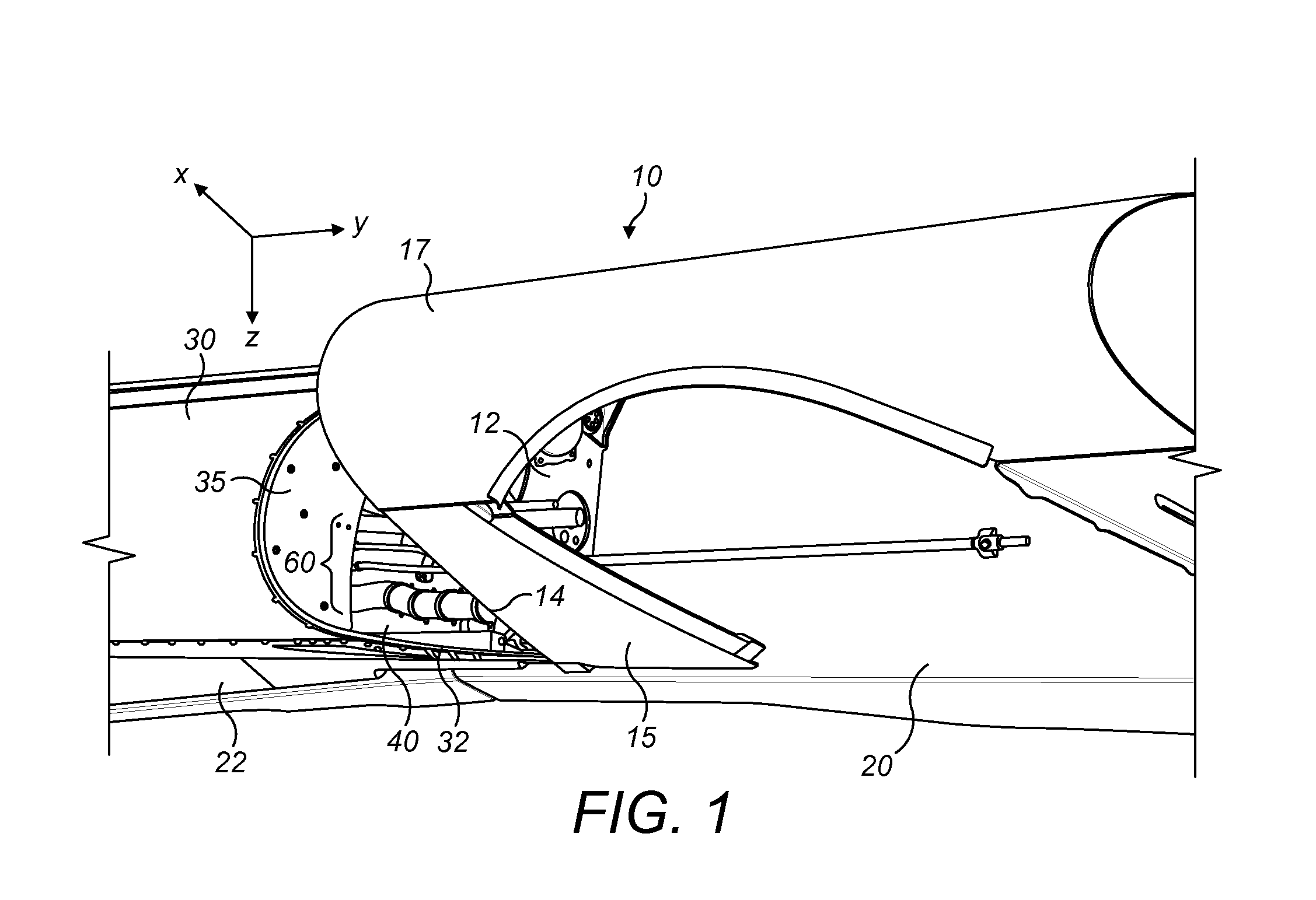
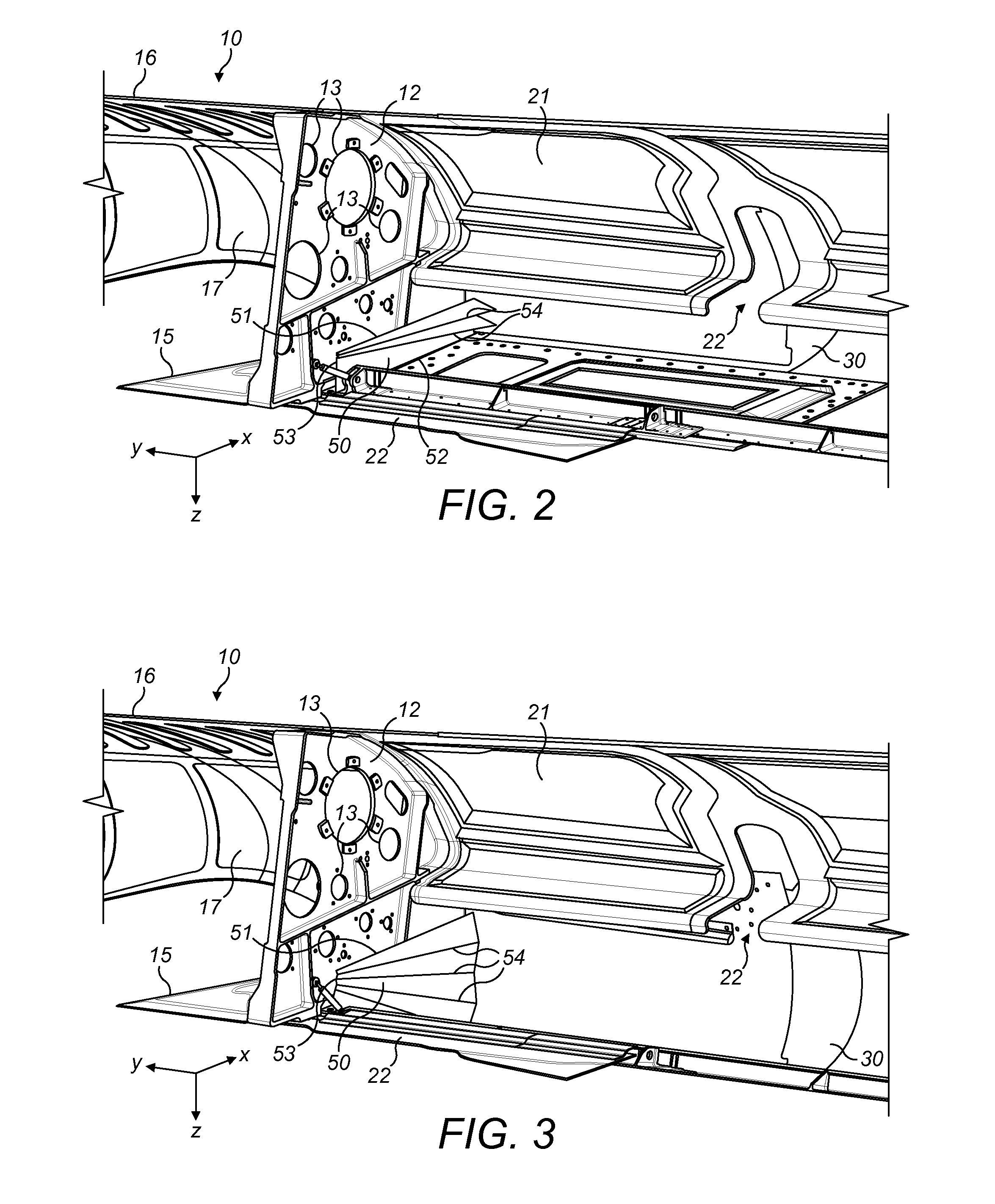
[0034]FIG. 1 shows a leading edge wing assembly with a fixed leading edge structure including a front spar 20 (omitted in FIGS. 2 and 3 for clarity), a fairing or nose structure 10 fixedly attached to the spar, and pylon primary structure (not shown) which serves to attach a gas turbine engine or other engine (now shown) to the wing. The fixed structure also includes an inboard closing rib 12, which provides a lateral barrier separating the pylon primary structure from a deployable droop nose device 30 located inboard of the fairing 10, and to which the fairing 20 is attached. Orthogonal xyz axes are shown in FIGS. 1-3—the x-axis indicating the forward direction, the y-axis the outboard direction (away from the centre of the aircraft) and z-axis the downward direction.

[0035]The fairing 10 has a curved forward nose part 17 which forms the foremost edge of the airfoil profile of the aircraft wing, and lower and upper parts 15, 16 which extend aft of the forward part 17 and provide lo...


PUM


Abstract

The present invention provides an aircraft assembly with a fixed structure and a high-lift device. The fixed structure has a spar, a forward part which provides a foremost edge of an aircraft wing, and a lower part which provides a lower surface of the aircraft wing. A high-lift device is downwardly movable relative to the fixed structure from a stowed configuration to a deployed configuration. The high-lift device has a forward part which provides a foremost edge of the aircraft wing and a lower part which provides a lower surface of the aircraft wing. Downward movement of the high-lift device causes progressive opening of a lateral gap between the lower part of the high-lift device and the lower part of the fixed structure. A retractable infill panel is arranged to progressively extend from a retracted configuration to an extended configuration to fill the lateral gap.

Description

FIELD OF THE INVENTION[0001]The present invention relates to a retractable infill panel for sealing a gap between a fixed leading edge structure of an aircraft wing and a movable high-lift device, in particular for preventing ingress of fire or debris.BACKGROUND OF THE INVENTION[0002]Some fixed wing aircraft have leading edge high-lift devices such as droop nose devices or slats which are downwardly movable relative to the fixed structure of the wing from a stowed configuration to a deployed configuration. Deployment of such devices relative to the fixed structure causes a lateral gap to progressively open between a lateral edge of the high-lift device and the fixed structure. Such gaps can cause systems and structure within the fixed wing structure to become exposed to the risk of fire or debris ingress, or can alternatively impose an aerodynamic penalty on the aircraft.[0003]Previous solutions have included a false floor attached to the fixed structure, but such a solution is not ...

Claims


Application Information

Patent Timeline
IPC IPC(8): B64D45/00
CPCB64D45/00B64C9/24
Inventor HODKISSON, MARKWILSON, JAMESEVANS, SAMUEL
Owner AIRBUS OPERATIONS LTD
Why Eureka
Try Eureka