Aerial sheave device

a technology of sheaving device and sheaving cable, which is applied in the direction of machine supports, instruments, other domestic objects, etc., can solve the problems of exacerbated cable suspension task, laborious installation task, etc., and achieves the effect of reducing stress, pressure and force, facilitating and improving the process of cable suspension

Active Publication Date: 2014-05-22
JAMESON LTD
View PDF15 Cites 20 Cited by
  • Summary
  • Abstract
  • Description
  • Claims
  • Application Information

AI Technical Summary

Benefits of technology

[0009]It is therefore an object of the present invention to provide an aerial sheave device that facilitates and improves the process of suspending cables. It is a further object of the invention to provide an aerial sheave device that reduces stress and pressure and forces applied to cables during installation. It is a further object of the invention to provide an aerial sheave device that prevents cable and cable extension such as pull tape from being damaged or lodged in various parts of the sheave such as in the wheel. It is a further object of the invention to provide an aerial sheave device that insulates a cable installer or operator from dangerous power transmission. It is a further object of the invention to provide an aerial sheave device that is lightweight, durable, and efficiently manufactured. It is a further object of the present invention to provide a plastic sheave wheel of a sheave that minimizes or eliminates peaks and valleys, especially in larger sheave wheels such that the wheel is substantially smooth and round.
[0010]These and other objects and advantages of the invention are achieved by providing an aerial sheave device for the installation and suspension of cable. The device enables an installation crew to safely install cable, especially fragile cable such as fiber optic cable, in environments that are difficult to reach, in environments where the cable may be damaged, and in environments where attachment points may be spaced far apart. The device prevents the damage to the cable from sharp bends. The device is designed so that, once engaged, the cable may not slip off of the pulley of the sheave unless the operator desires the cable to be removed. The device is designed to be flexible and move in many directions so that the cable does not bind or detrimentally bend or jam during installation. The device is preferably made from non-conductive material such as plastic.
[0011]According to an embodiment, the sheave is designed to withstand typical forces experienced during the process of pulling aerial fiber optic cable lines from pole to pole. This feature is especially important for the fiber optic cable installation as the cable can easily break or become damaged when too much tension is applied. The sheave is preferably entirely made from plastic, though some parts such as springs and fasteners may be metal, and there may also be an internal, non-exposed metal insert to improve rigidity, and all exposed surfaces have a high dielectric strength and are non-conductive. The exposed surfaces are preferably made from nylon or thermoplastic polyurethane. Any exposed metal surfaces may be shielded in some fashion to prevent accidental contact.
[0012]According to an embodiment of the invention, the aerial sheave may include a pulley wheel which rotates around an axle attached to a frame. The frame may include a rigid side, a top side, and a latch side. A latch is attached to the latch side of the frame. The latch provides access to the wheel of the sheave and the latch may operate from an open to a closed position. The latch may include a spring loaded plunger which may be biased in the closed position. The plunger may secure the latch to the frame in the closed position. The sheave may further include a swivel-loop attachment. The swivel-loop attachment may include a loop portion which extends above the top side of the frame and a semispherical solid dome portion which fits within a semispherical dome cavity portion of the top side of the frame. The sheave may further include a locking guard which is attached to the frame. The locking guard may operate from a locked position to an unlocked position. The locking guard may have a spring for biasing the guard in the unlocked position and may also have a lever for locking the guard in the locked position. According to such a locking guard, a turn of the lever in a first direction will unlock the guard and another turn of the lever in an opposite direction in combination with pressure applied against the spring will lock the guard. Further, the combination of the locking guard and wheel opening comprises a size and shape (rounded edges) so as to allow standard cable splice technologies and adjunction installation aides such as attached pull grips to easily pass through the opening with minimal drag.
[0013]According to another embodiment of the invention, the latch side may be located on either a left or a right side of the frame. Further, the latch may be attached to the frame via hinge connection or via a pivot pin connect. Where a hinge connection is utilized, when the latch is in the open position, the latch swings out and away from the top side of the frame about the hinge towards a lower end of the pulley wheel. Where a pivot pin connection is utilized, when the latch is in the open position, the latch rotates parallel to the frame and towards a lower end of the pulley wheel. The latch may further include a stop tab which secures the latch to the frame in the closed position and also prevents the latch from swinging about the pin beyond 130 degrees in either direction when in the operating position. The tab also allows the swing latch to swing far enough that it does not interfere with the loading or removal of cable.
[0021]According to an embodiment of the invention, the sheave includes a swivel loop arrangement rotatingly attached to the top side of the frame. The swivel allows the frame, and thus the pulley on the axle, to swivel 360 degrees and the loop allows the frame to rotate from vertical to horizontal. The loop is an elongate loop having a central open cavity. The swivel mechanism utilizes a dome-inside-a-dome connection. This dome-inside-a-dome connection includes a dome shape cavity, in the shape of an approximate semisphere cavity, formed within the top side of the frame. A slightly smaller solid dome, in the shape of an approximate semisphere, that matches the shape of the dome shape cavity, fits within and rotates within the dome shape cavity. This solid dome is fixedly attached to a solid cylindrical portion which is then attached to the loop. The smaller dome is thus embedded within the dome cavity of the frame and is made from plastic. In use, the loop is attached to some fixed point, such as a hook, bolt, tie, rope, or other connection on a pole. The entire device may then rotate horizontal to vertical via the loop and may also rotate in a 360 degree circle via the swivel dome-inside-a-dome connection. Thus, the cable being pulled may come from an adjacent pole or from a ground spool. Similarly, the cable being pulled may be going onto a pole located at any angle or to a ground puller. In each of these instances, the fiber optic cable will not be damaged.

Problems solved by technology

Though the suspension of cables on poles and other overhead structures has many benefits, there are also disadvantages related to installation.
As cables can be strung for runs of thousands of feet, and indeed miles, the task of suspending cables from pole to pole can be labor intensive.
The task of suspending cables is exacerbated when the cables are fragile.
Whereas a copper electrical cable may withstand significant pulling, bending, and wear during a process of suspension, fragile cables such as fiber optic cables may easily become damaged during overhead installation.
This damage can occur when too much pressure or stress is applied to a cable.
This damage can occur when a cable bends too sharply around a corner.
This damage can occur when the cable gets caught around the axle of a pulley in prior sheave art.
The damage can also occur when various parts, such as latches, of prior art sheaves become detached such that the cable becomes removed from the prior art sheaves.
This damage can also occur because prior art sheaves have no way to retain the cable as it tightens or slackens while it is being pulled.
Damage may also occur when splices in cable become lodged in the sheave causing undue strain or stress on the cable such as when an operator does not stop pulling the cable in time to prevent damage to the cable.
Damage to fragile cables can also occur when the profile or “floor” of a sheave is not uniformly round.
One problem in the art occurs when sheaves are made of plastic.
This shrinkage differential can cause the floor of the pulley wheel to have peaks and valleys.
Peaks and valleys in the wheel act to defeat the benefits of a wheel in the first place and importantly can damage fragile fiber optic cable.
Further, as cables often carry electrical current, there is a risk that those who install such cables or who operate and install other cables which are close to power cables may become electrocuted.

Method used


Image

  • Aerial sheave device
  • Aerial sheave device
  • Aerial sheave device

Examples


Embodiment Construction

[0050]The present discussion is a description of exemplary embodiments only and is not intended as limiting the broader aspects of the present invention. The following example is provided to further illustrate the invention and is not to be construed to unduly limit the scope of the invention.

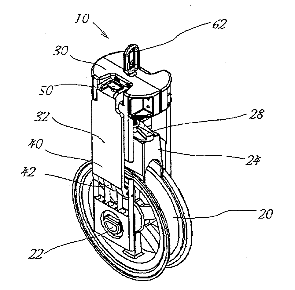
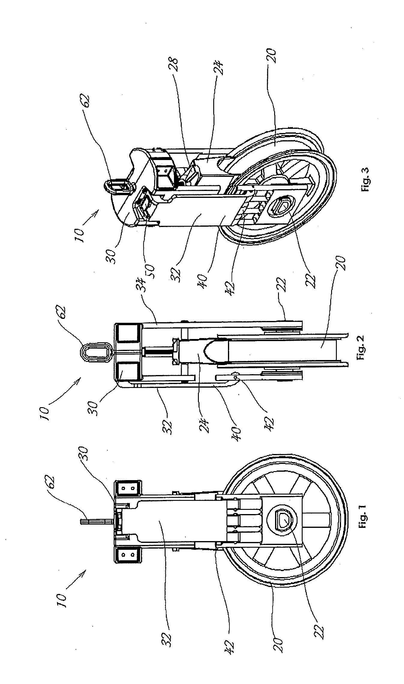
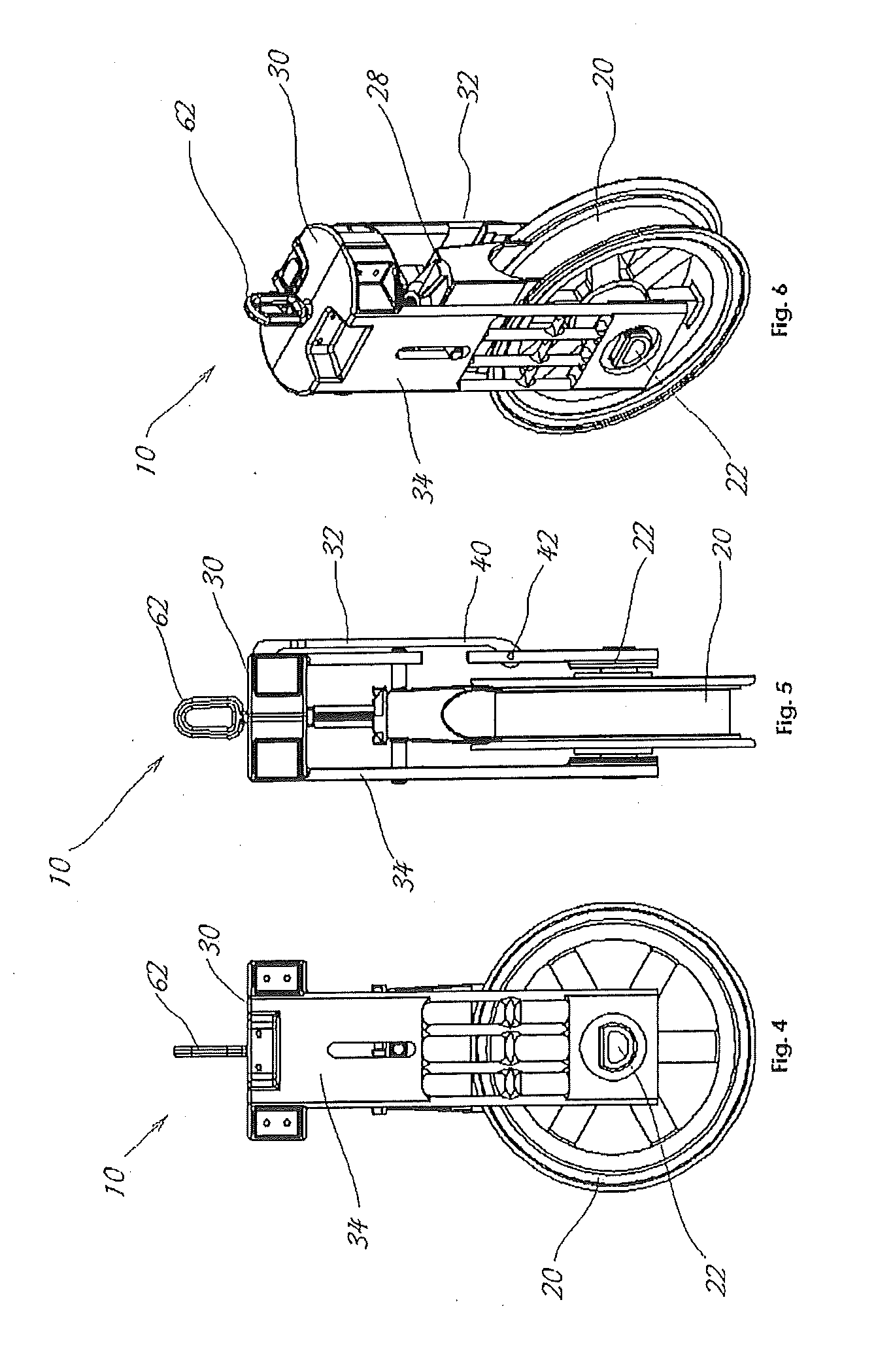
[0051]Referring to the drawings wherein identical reference numerals denote the same elements throughout the various views, FIGS. 1-10 are directed to an embodiment of the sheave 10 having a pulley wheel 20 that rotates on an axle 22. The wheel 20 is circular and has a generally “U” shaped profile that cradles a cable 90 that operates on the wheel 20 as shown in the environmental views of FIGS. 22 and 23. The axle 22 is attached to a frame that has a top side 30, a latch side 32, and a rigid side 34. A cable guard 24 is also attached to the frame and the cable guard 24 has a generally inverted “U” shape that coordinates with the “U” shape of the wheel 20. The way in which the “U” shape of the w...


PUM


Abstract

Disclosed is an aerial sheave device for the installation and suspension of cable. The aerial sheave device includes a frame and a rotating wheel that coordinates with a locking cable guard. The device also includes a lockable side latch for affording access to the wheel area. The frame may be attached to a utility pole via a loop attached to the frame. The loop attaches to the frame via dome-inside-a-dome connection which allows the frame to also rotate 360 degrees. The dome-inside-a-dome connection includes a solid semispherical dome attached to the loop which fits inside a slightly larger semispherical dome shaped cavity of the frame.

Description

[0001]This application is a non-provisional of, incorporates by reference, claims the benefit of, and claims priority to co-pending, U.S. Provisional Application having Ser. No. 61 / 727,363 filed on Nov. 16, 2012.TECHNICAL FIELDBackground of Invention[0002]The invention relates to the field of cable installation. More particularly, the invention relates to the field of the installation of suspended cable such as fiber optic cable suspended in the air via poles which are anchored to the ground.[0003]In the field of cable installation, cables are often suspended overhead on utility poles. Though telegraph cables were the first cables to be suspended on poles in the Nineteenth Century after buried cable proved faulty, today many cables are suspended. Suspending cables overhead is an inexpensive way to both insulate the cables from the ground and to keep them out of the way of people, vehicles, structures, paths, roads, and the like. Power cables used for distribution and subtransmission...

Claims


Application Information

Patent Timeline
Patent Type & Authority Applications(United States)
IPC IPC(8): F16L3/18
CPCF16L3/18G02B6/483H02G1/04
Inventor JONES, THOMAS LEE
Owner JAMESON LTD
Why Eureka
Try Eureka