Method and system for a universal NMR/MRI console

a console and nmri technology, applied in the field of methods and systems for universal nmr/mri consoles, can solve the problems of incompatibility of systems produced by different manufacturers, inability to use in general a controller intended for one manufacturer's instrument with a magnet supplied by another manufacturer, and no address of these devices

Active Publication Date: 2014-05-22
ASPECT IMAGING
View PDF1 Cites 60 Cited by
  • Summary
  • Abstract
  • Description
  • Claims
  • Application Information

AI Technical Summary

Problems solved by technology

One problem faced by the user of NMR / MRI systems is the incompatibility of systems produced by different manufacturers.
Even in the simplest case of two systems with identical magnets and systems being probed, where the RF pulses in principle should be identical, one cannot in general use a controller intended for one manufacturer's instrument with a magnet supplied by another manufacturer.
None of these devices address the main reason for these incompatibilities, namely, that the digital signal sent from the console to the various signal generators (e.g. those that deliver the magnetization RF pulses, gradient field pulses, etc.) in order to produce a desired analog output to the spectrometer is not uniform across manufacturers.

Method used


Image

  • Method and system for a universal NMR/MRI console
  • Method and system for a universal NMR/MRI console
  • Method and system for a universal NMR/MRI console

Examples


Embodiment Construction

[0027]In the following description, various aspects of the invention will be described. For the purposes of explanation, specific details are set forth in order to provide a thorough understanding of the invention. It will be apparent to one skilled in the art that there are other embodiments of the invention that differ in details without affecting the essential nature thereof. Therefore the invention is not limited by that which is illustrated in the figure and described in the specification, but only as indicated in the accompanying claims, with the proper scope determined only by the broadest interpretation of said claims.

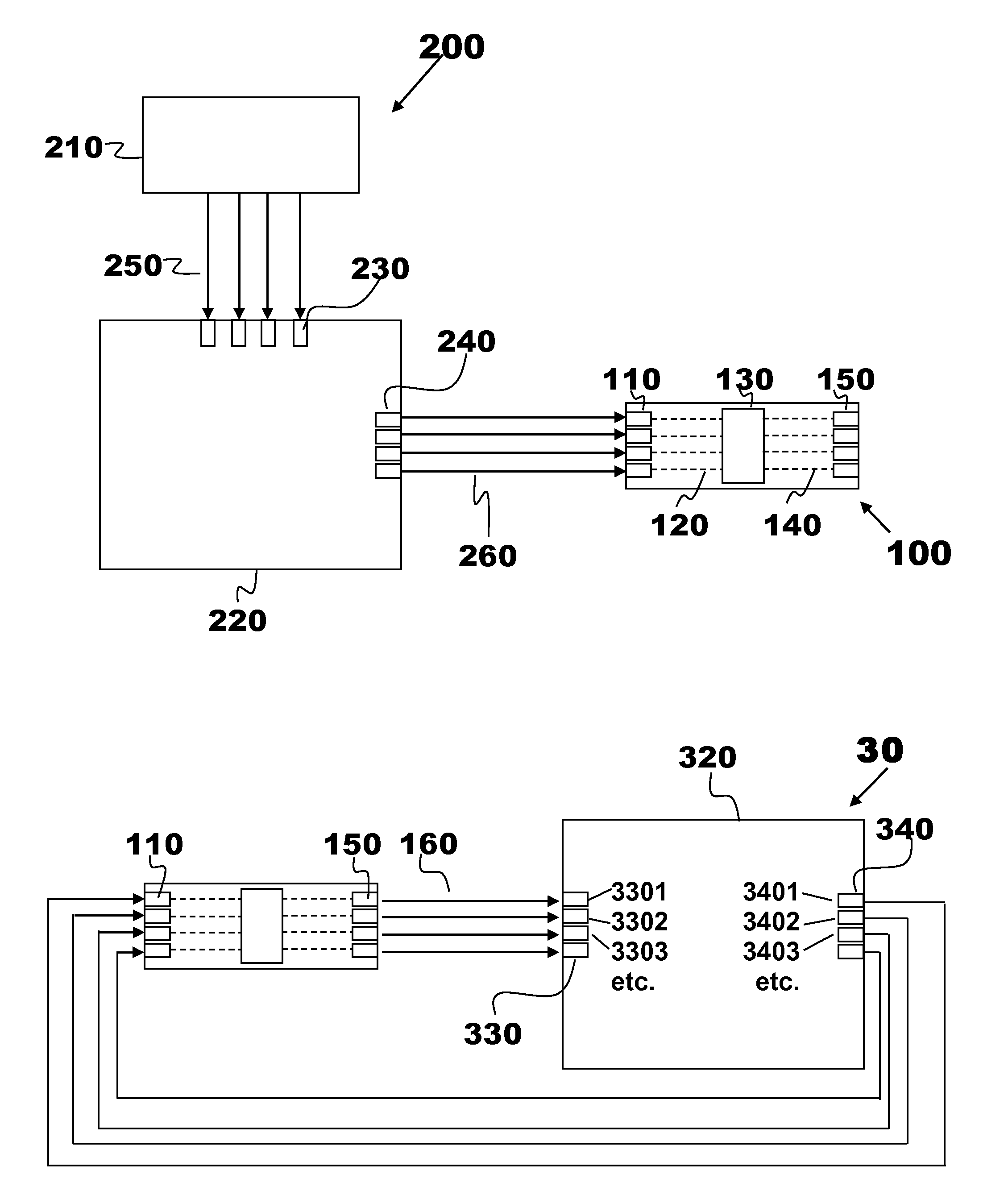
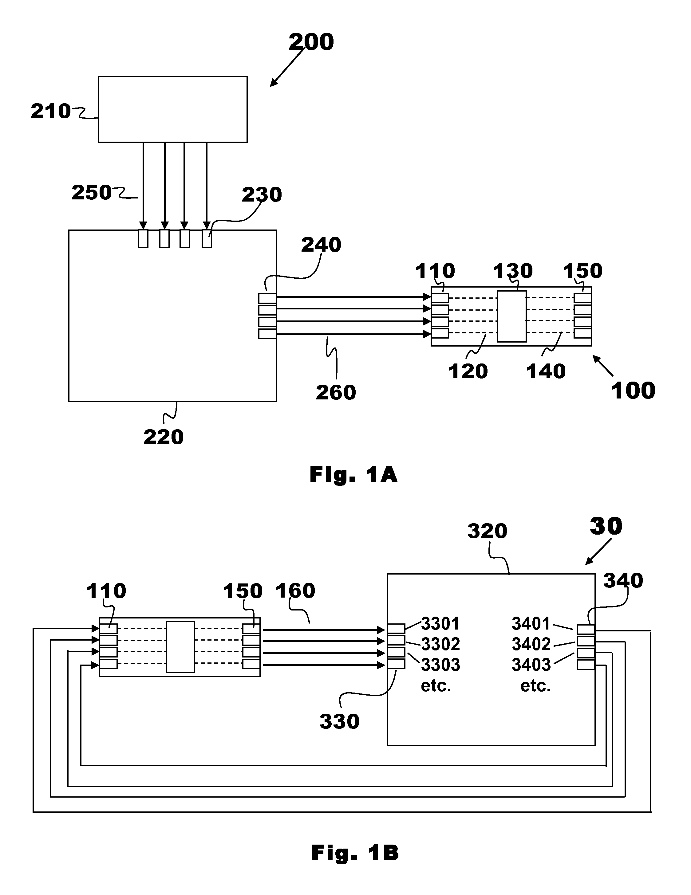
[0028]The invention herein disclosed relates to methods and systems for controling pulsed magnetic resonance systems. As used herein, the term “pulsed magnetic resonance system” refers to a system for making measurements using a spectroscopic method that relies on transitions occurring in a magnetic field and that involves providing energy to the species being ...


PUM


Abstract

A method and system are provided for providing values for control signals for a pulsed magnetic resonance spectrometer such as an NMR spectrometer or an MRI apparatus. The AC output(s) corresponding to a particular signal (e.g. a magnetization or gradient pulse or pulse sequence) originating from a source spectrometer is measured and stored by an independent control unit. The digital output of the independent control unit is then connected to the digital input of the control electronics of a target pulsed magnetic resonance spectrometer, the value of the digital output varied until the AC output(s) of the appropriate signal source of the target spectrometer matches that of the corresponding output(s) of the source spectrometer, corrected, if necessary, for differences in magnetic field strengths.

Description

FIELD OF THE INVENTION[0001]This invention relates in general to means and methods for emulating the controller of an MRI spectrometer. It relates particularly to a method and system for monitoring the spectrometer's RF signals and reproducing those signals with a generic MRI spectrometer controller.BACKGROUND OF THE INVENTION[0002]NMR and MRI are among the most widely used spectroscopic techniques, finding uses in fields ranging from chemical analysis to medical imaging. One problem faced by the user of NMR / MRI systems is the incompatibility of systems produced by different manufacturers. The amount of RF power needed to effect a desired change in the magnetization of a sample inside an NMR spectrometer depends only on the magnetic field strength and the gyromagnetic ratio of the nucleus being probed. Even in the simplest case of two systems with identical magnets and systems being probed, where the RF pulses in principle should be identical, one cannot in general use a controller ...

Claims


Application Information

Patent Timeline
Patent Type & Authority Applications(United States)
IPC IPC(8): G01R33/54
CPCG01R33/54G01R33/3607G01R33/3852
Inventor RAPOPORT, URI
Owner ASPECT IMAGING
Why Eureka
Try Eureka