Medical thermometer having an improved optics system

a thermometer and optics system technology, applied in the field of medical thermometers with improved optics systems, can solve the problems of temperature differences and more problems in the second summand, and achieve the effect of reducing the amount of stray radiation

Inactive Publication Date: 2014-05-22
HELEN OF TROY LIMITED
View PDF3 Cites 1 Cited by
  • Summary
  • Abstract
  • Description
  • Claims
  • Application Information

AI Technical Summary

Benefits of technology

[0016]A non-contact IR thermometer according to various embodiments of the present invention includes, among other things, an IR radiation sensor having a sensor surface, which may be coupled to a filter positioned in the sensor's field of view that may be capable of passing only radiation having a desired range of wavelengths; a mirror, which may be parabolic or approximately parabolic in shape and may include surfaces and curvatures based on elliptic paraboloids, the sensor being positioned at or near a focal point of the mirror and the filter being positioned between the sensor and the mirror; and an aperture that is outside the sensor's direct field of view, the mirror providing a radiation path between the filter and the aperture. In various embodiments, the sensor may be included as a component on a semiconductor device that possesses various additional functionalities as will be understood by those having ordinary skill in the art. Additionally, in various embodiments, the center of the sensor surface may be positioned at or near the focal point of the mirror and the surface of the sensor may be oriented at various angles with respect to the baseline of the mirror to further minimize the amount of stray radiation reaching the sensor, which may be determined or understood as a percentage of total radiation. In various embodiments, the angle between the baseline of the mirror and the normal to the surface of the mirror is between approximately 25° and 35°. In other embodiments, this angle is approximately 31.5°. In various embodiments the aperture may include, be covered by, or have disposed adjacent thereto a protective window and / or filter that can prevent radiation of certain undesired wavelengths from passing therethrough.

Problems solved by technology

Practically, these temperatures may differ as the result of, e.g., measurement error or calibration drift.
The second summand can be more problematic, especially due to a generally unknown and unpredictable value of the object's emissivity εb.

Method used


Image

  • Medical thermometer having an improved optics system
  • Medical thermometer having an improved optics system
  • Medical thermometer having an improved optics system

Examples


Embodiment Construction

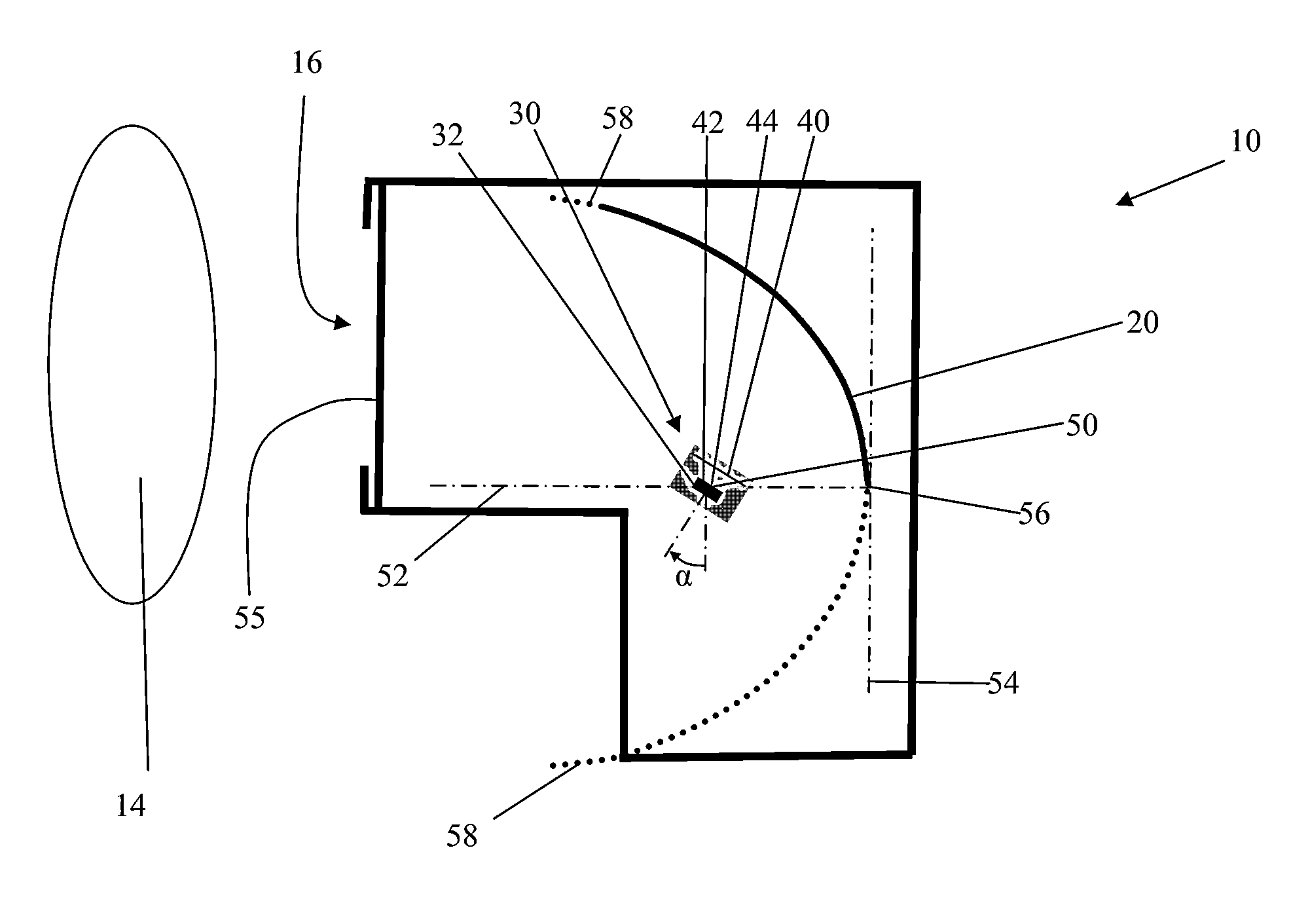
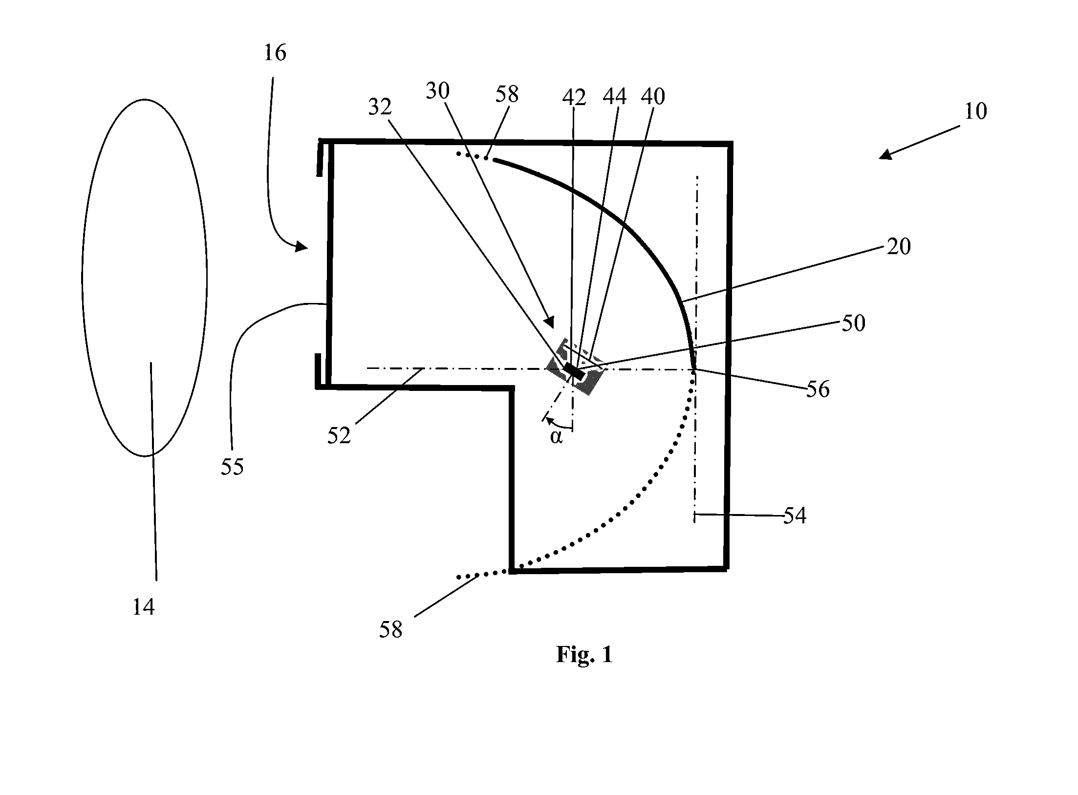
[0025]A remote IR thermometer is disclosed that includes, among other things, a parabolic or approximately parabolic mirror and an IR radiation sensor assembly including a filter component and a sensor component. The sensor component includes a surface with a geometric center point on the surface that is positioned in the vicinity of the mirror's focal point. The sensor component may be oriented about the center point at various angles. For the purpose of illustrating principles in accordance with various embodiments of the present invention, several non-limiting examples of the various embodiments are described below. Accordingly, the scope of the invention should be understood to be defined only by the scope of the claims and their equivalents, and not limited by the example embodiments.

[0026]FIG. 1 shows a schematic, cross-sectional view of an embodiment of the mirror 20 and sensor assembly 30 inside a remote IR thermometer 10 having a radiation entrance, e.g., aperture 16 that m...


PUM


Abstract

A medical thermometer including a curved mirror and a radiation sensor is disclosed. The radiation sensor is disposed relative to the mirror in a configuration whereby the mirror reflects away from the sensor radiation that passes through the radiation entrance and that is oriented outside a range of angles relative to the mirror, and reflects toward the sensor radiation that passes through the radiation entrance and that is oriented within a range of angles relative to the mirror.

Description

CROSS-REFERENCES TO RELATED APPLICATIONS[0001]This application claims priority to U.S. provisional application No. 61 / 728,003, filed Nov. 19, 2012, the disclosure of which is incorporated herein by reference in its entirety.FIELD OF THE INVENTION[0002]The present invention relate generally to devices for measuring temperature, and more specifically to non-contact infrared thermometers for medical applications incorporating mirrors to reduce the effects of stray radiation.DESCRIPTION OF RELATED ART[0003]A thermal radiation or infrared (IR) thermometer is a device capable of measuring temperature without physically contacting the object of measurement. Thus, such thermometers are often called “non-contact” or “remote” thermometers. In an IR thermometer, the temperature of an object is taken by detecting an intensity of the IR radiation that is naturally emanated from the object's surface. For objects between about 0° C. and 100° C., this requires the use of IR sensors for detecting ra...

Claims


Application Information

Patent Timeline
Patent Type & Authority Applications(United States)
IPC IPC(8): G01J5/08
CPCG01J2005/065G01J5/0831G01J5/0011G01J5/06G01J5/0806G01J5/0808
Inventor YILDIZYAN, ALEKSANGORSICH, JAMES CHRISTOPHER
Owner HELEN OF TROY LIMITED
Why Eureka
Try Eureka