Small Form-Factor Pluggable Optical Transceiver

a technology of plugging and optical transceivers, applied in the field of optoelectronic communication and devices, can solve the problems of inability to eliminate overheating of optical devices, relatively low efficiency, and inability to overheat optical devices, so as to improve yield, increase thermal issues, and increase port densities

Active Publication Date: 2014-05-22
SOURCE PHOTONICS CHENGDU
View PDF14 Cites 2 Cited by
  • Summary
  • Abstract
  • Description
  • Claims
  • Application Information

AI Technical Summary

Benefits of technology

[0009]Preferably, the casing has an internal isolator configured to divide the casing into a first cavity to accommodate the optical devices and a second cavity to accommodate the electrical devices. As a result, the relatively high heat produced by the electrical device portion during normal operation may be reduced or eliminated from being transferred to the cavity where the optical devices are located. As a result, the operating temperatures of the optical devices are reduced.
[0010]Alternatively, during normal operation, the first cavity is located outside the switchboard, and the second cavity is located inside the switchboard. In this configuration, the effect of the high temperature inside the switchboard on the first cavity containing the optical devices can be minimized during normal operation. Thereby, the heat produced by the electrical device portion may be prevented from being transferred to the internal portion of the first cavity. In addition, the heat outside the casing and / or inside the switchboard affecting the operating temperature of the optical device may be prevented. Furthermore, the operating temperature of the optical device may be kept at a relatively low level, thereby increasing the life and efficiency of the optical device.
[0012]In various embodiments of the present invention, air holes are located in the cover and base of the casing corresponding to the first cavity. The air holes run through the casing and communicate the first cavity with the outside of the casing. In this structure, heat in the first cavity containing the optical devices can be exchanged with the air outside the device more effectively. Preferably, the air holes are arranged in the cover and the base of the casing in predetermined positions or locations. In this structure, heat in the first cavity can be exchanged with the air outside the device steadily and effectively.
[0013]In further embodiments of the present invention, a bottom surface (e.g., face) of the casing has a tapered end, and the isolator has a groove compatible (e.g., configured to mate) with the tapered end. The connection between the isolator and the casing is implemented by the tapered end fitting or mating with the groove, resulting in efficient heat insulation.
[0015]Thus, the present invention relates to a two-cavity SFP optical transceiver module that can operate at two different temperatures in different regions of the module. Generally, the ambient temperature outside of the module, switch or switchboard is less than 55° C., but the temperature inside the module, switch or switchboard may exceed 75° C. The temperature of the extended nose (e.g., the tapered end or optical cavity of the transceiver) is the case temperature of the switch or switchboard, with which the optical subassembly (OSA) inside the optical cavity will be in thermal equilibrium. In addition, the temperature of the extended nose will be cooler than the temperature of the electrical (or back) portion of the transceiver, which is the temperature of the electronic parts inside the SFP casing. The present invention advantageously provides a two-part casing structure that can operate at different temperatures, having an extended nose (e.g., tapered end) and two operating temperature zones. Generally, higher port densities may increase thermal issues inside the system (e.g., a switch). The optical portion of the present transceivers should stay at a temperature ≦85° C. Lower OSA temperatures advantageously provide improved yields, lower operational costs, and / or better performance.
[0016]Relative to the conventional devices described above, the present invention advantageously locates optical devices that are sensitive to operational temperature outside the switchboard or system case. Relative to accommodating the operational temperature of the optical devices when heated inside the switchboard, a reduction in the operational temperature of the optical device portion of the transceiver improves operational performance and extends the life of the device. Also, placing the optical device portion outside the switchboard advantageously improves the cooling of the optical devices.

Problems solved by technology

However, overheating of the optical device cannot be eliminated.
Generally, overheating of the optical device occurs after connecting the SFP optical transceiver to the switchboard, since the electrical and optical devices of the SFP optical transceiver are completely enclosed in the switchboard.
The switchboard and the electrical devices of the SFP optical transceiver emit a significant amount of heat during normal operation, creating a relatively hot environment within the device, thereby resulting in relatively low efficiency and a decrease in the life of the device.
As optical and electrical devices are placed in one cavity in the conventional SFP optical transceiver, high heat close to the electrical device could easily transfer to the optical device, negatively affecting the performance and the life of the optical device.

Method used


Image

  • Small Form-Factor Pluggable Optical Transceiver
  • Small Form-Factor Pluggable Optical Transceiver
  • Small Form-Factor Pluggable Optical Transceiver

Examples


embodiment 1

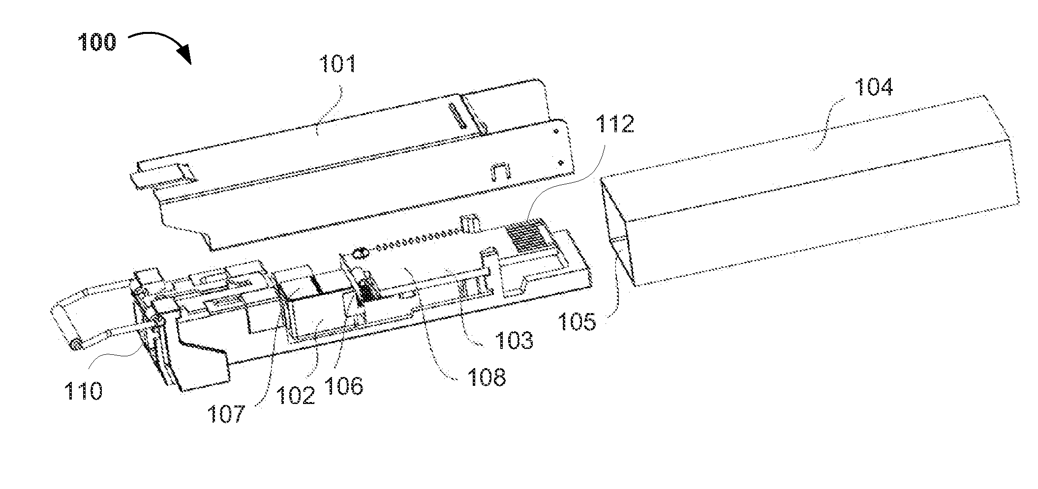
[0028]As shown in FIG. 1, a small form-factor pluggable (SFP) optical transceiver 100 comprises a casing 101 having an optical port 110 and an electrical port 112. The casing 101 is configured to accommodate optical devices 102 and electrical devices 103. The optical device 102 comprises a transceiver optical subassembly (TOSA) and a receiver optical subassembly (ROSA). The electrical devices 103 are located on a printed circuit board (PCB) on or near the bottom of the casing 101.

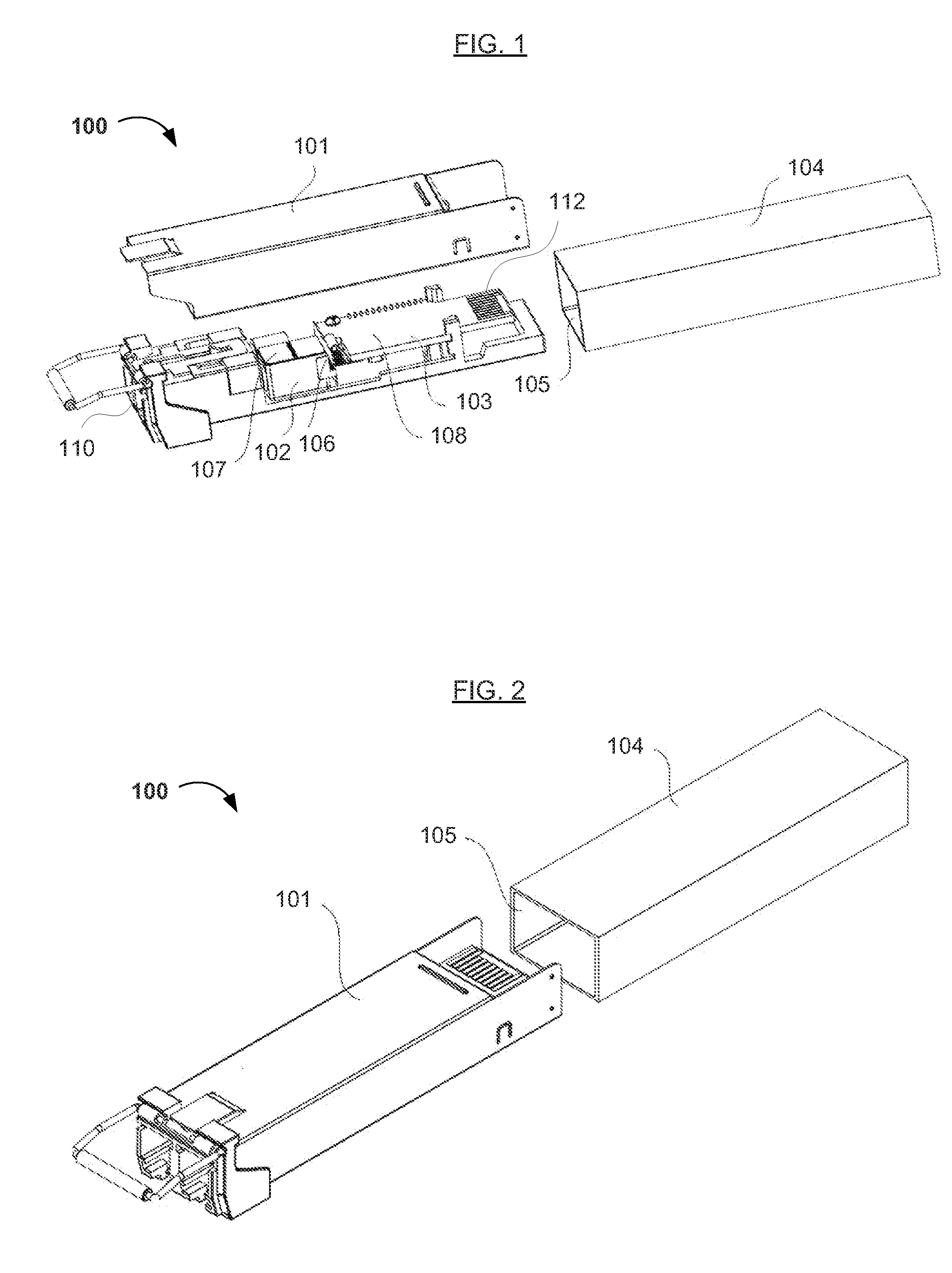
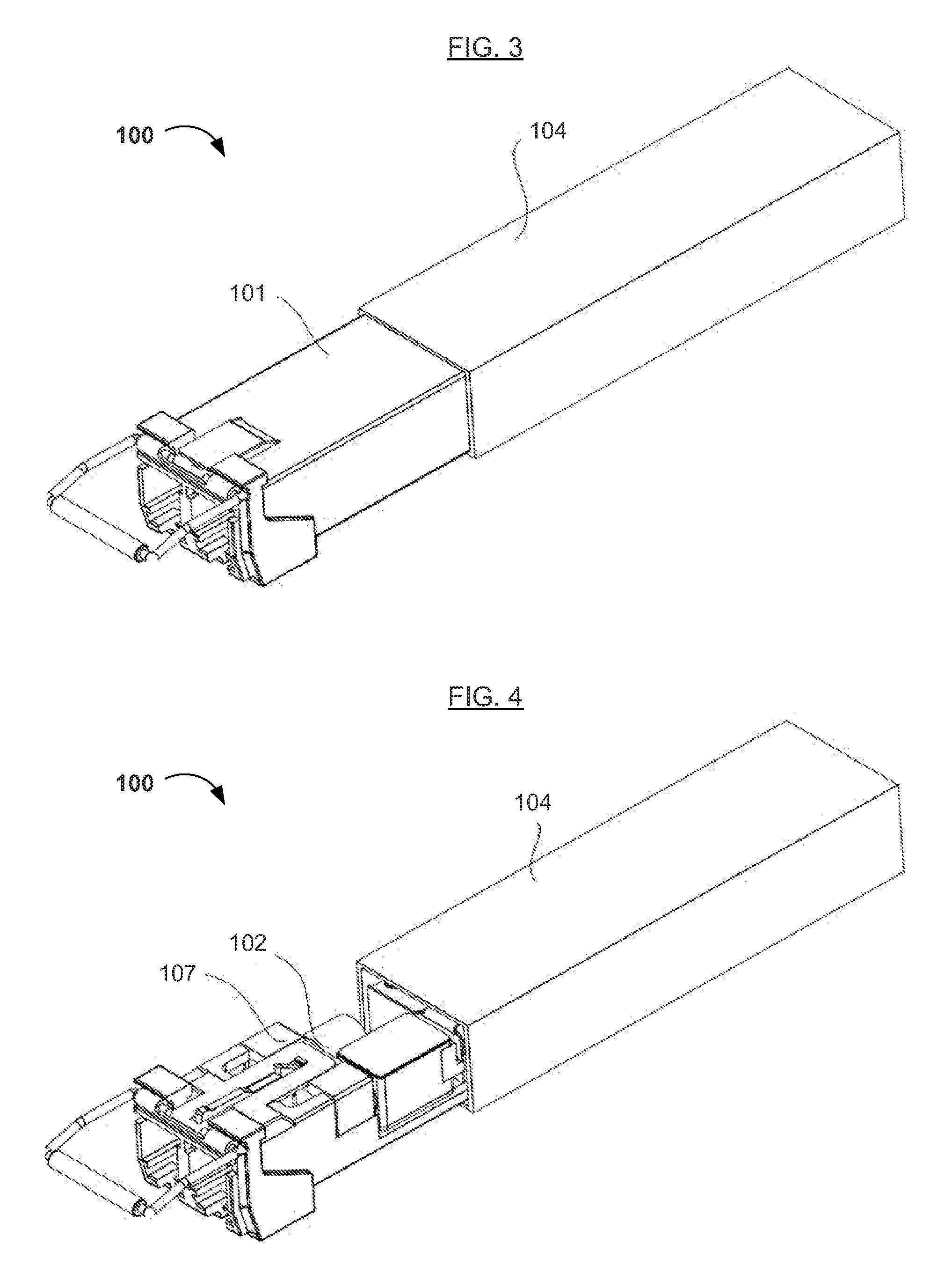
[0029]As shown in FIGS. 2-4, during normal operation, the casing 101 is connected to a switchboard 104 via a connector 105 located in the switchboard 104. As shown more clearly in FIG. 3, one portion of the casing 101 stays outside of the switchboard 104 after the casing 101 is inserted into the connector 105 located in the switchboard 104. More specifically, the electrical devices 103 inside the casing 101 and the portion of the casing 101 enclosing the electrical devices 103 stay inside the switchboard 10...

embodiment 2

[0031]As shown in FIGS. 5 and 6, based on or from Embodiment 1 above, an SFP optical transceiver 200 (or a casing 201 therefor) has a built-in (e.g., internal) isolator 206. The isolator 206 is configured to divide the transceiver 200 (or casing 201) into a first cavity 207 close to or facing the optical port 210 and a second cavity 208 close to or facing the electrical port 212. The optical devices (not shown) are located in the first cavity 207, and the electrical devices (not shown) are located in the second cavity 208. After the transceiver 200 (or casing 201) is divided into two relatively independent cavities via the isolator 206, the portion 208 containing the electrical devices having a relatively high temperature is isolated from the portion 207 containing the optical devices. Heat produced by the electrical device portion 203 having a high temperature during normal operation can be blocked from being transferred to the cavity 207 where the optical devices are located, resu...

embodiment 3

[0036]Referring back to FIGS. 1 and 4, Embodiment 3 is different from directly setting the isolator 106 inside the casing 101, as described in Embodiment 2 above. In this embodiment (e.g., Embodiment 3), the isolator 106 and the casing 101 may be connected by a latching mechanism. More specifically, a bottom surface (e.g., face) of the casing 101 may have a tapered end, and the isolator 106 may have a groove compatible with the tapered end. The connection between the isolator 106 and the casing 101 is implemented by the tapered end effectively working or mating with the groove. Consequently, the optical device portion 102 may be easily removed or dismounted, and the connection between the optical devices 102 and the electrical devices 103 may be enhanced.

[0037]The other structures of this embodiment (e.g., Embodiment 3) have been explained in greater detail with respect to Embodiments 1 and 2.


PUM


Abstract

A small form-factor pluggable (SFP) optical transceiver includes a casing configured to accommodate optical and electrical devices. During normal operation, the casing is connected to a switchboard via a connector in the switchboard, and the optical devices are outside the switchboard, thereby exposing optical devices sensitive to high temperature to the outside air, reducing the operational temperature of the optical device portion relative to the heated portion inside the switchboard. Thus, the present SFP optical transceiver advantageously improves operational performance and extends the life of the device. Also, the present SFP optical transceiver having the optical device portion outside the switchboard advantageously improves the cooling performance for the optical device portion.

Description

CROSS REFERENCE TO RELATED APPLICATION[0001]This application claims the benefit of Chinese Patent Application No. 201210471478.3, filed on Nov. 20, 2012, which is incorporated herein by reference as if fully set forth herein.FIELD OF THE INVENTION[0002]The present invention generally relates to the field of optoelectronic communications and devices therefor, and particularly to an optical transceiver. More specifically, embodiments of the present invention pertain to a small form-factor pluggable (SFP) optical transceiver, particularly circuits, devices, and method(s) of making and / or using the same.DISCUSSION OF THE BACKGROUND[0003]A small form-factor pluggable (SFP) optical transceiver, generally defined by an applicable MSA standard, provides bidirectional data transmission in optical communications. Generally, a conventional SFP optical transceiver comprises (i) a casing, (ii) electrical devices, such as printed circuit boards (PCB), chips, etc., and (iii) optical devices, such ...

Claims


Application Information

Patent Timeline
Patent Type & Authority Applications(United States)
IPC IPC(8): G02B6/36
CPCG02B6/4273G02B6/36G02B6/4246G02B6/4292
Inventor HEIMBUCH, MARKWAINWRIGHT, WAYNE
Owner SOURCE PHOTONICS CHENGDU
Why Eureka
Try Eureka