Hand dryer

a dryer and hand technology, applied in the field of hand dryers, can solve the problems of excessive noise, frequent heavyness of the fan unit, and vibration, and achieve the effect of reducing vibration transmission

Inactive Publication Date: 2014-05-22
DYSON TECH LTD
View PDF18 Cites 7 Cited by
  • Summary
  • Abstract
  • Description
  • Claims
  • Application Information

AI Technical Summary

Benefits of technology

[0021]The hand dryer may be a wall-mountable hand dryer. It is particularly advantageous in such dryers to redu

Problems solved by technology

The fan unit will often be relatively heavy, and subject to vibration in use (caused by rotor im

Method used


Image

  • Hand dryer
  • Hand dryer
  • Hand dryer

Examples


Embodiment Construction

Hand Dryer

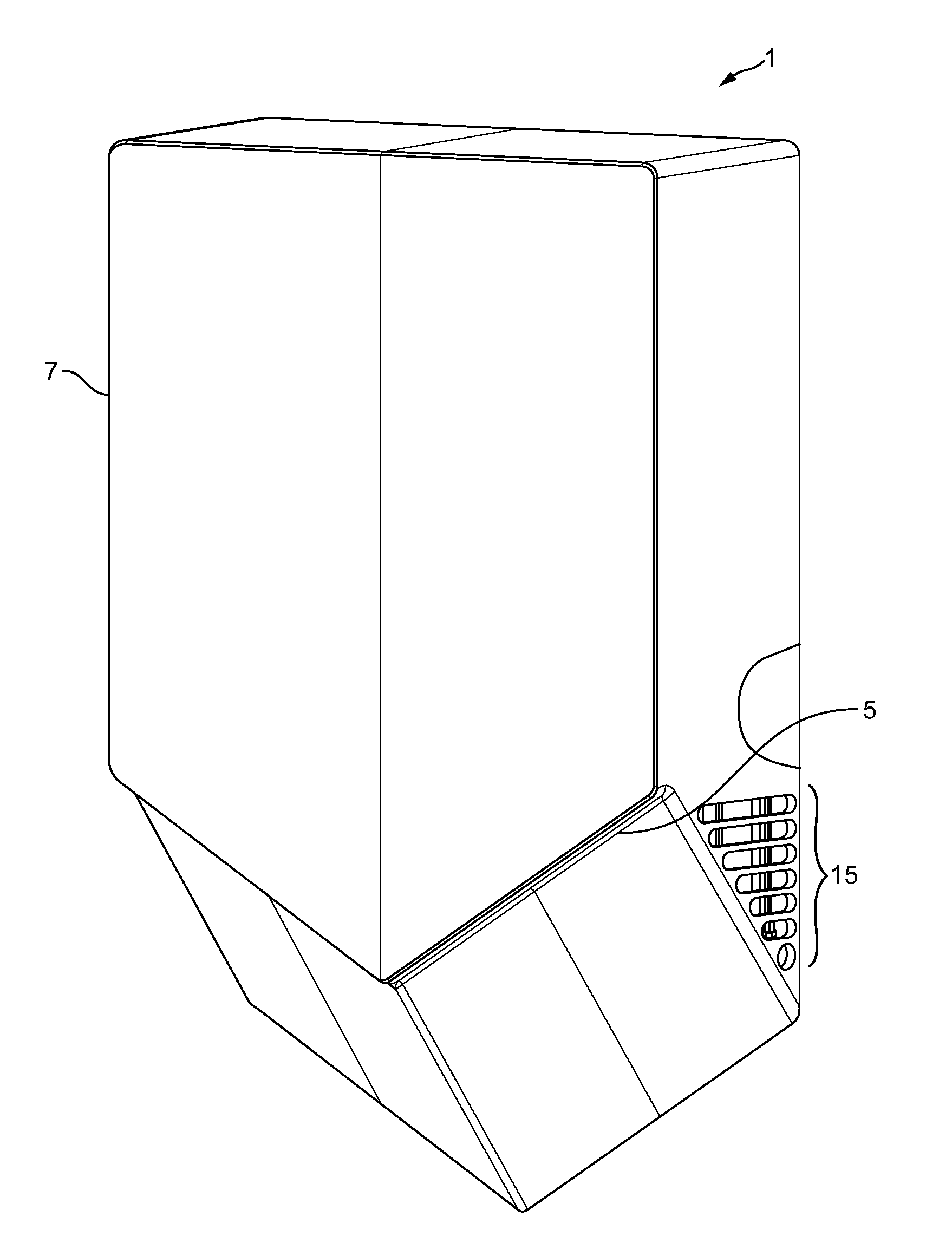
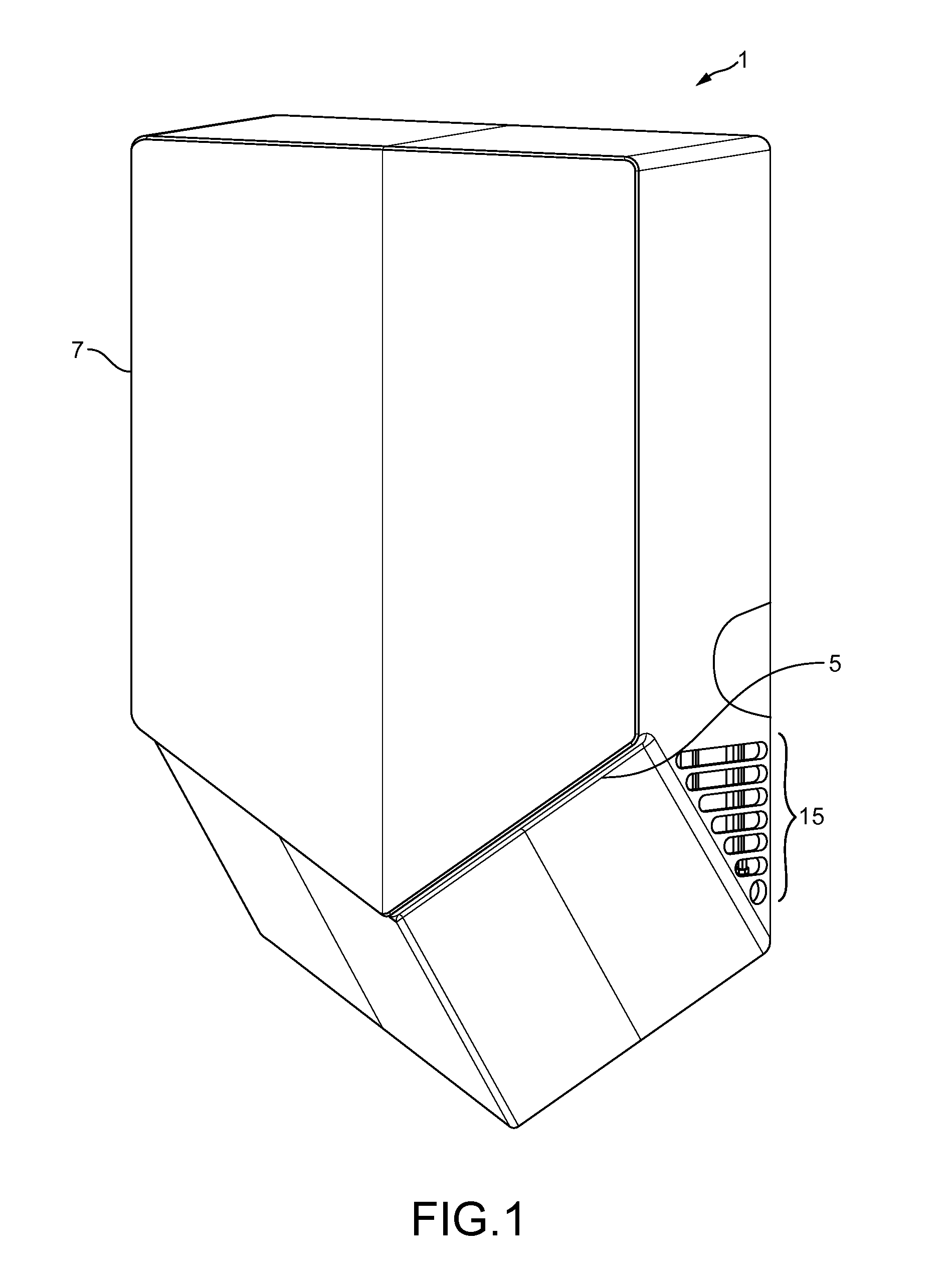
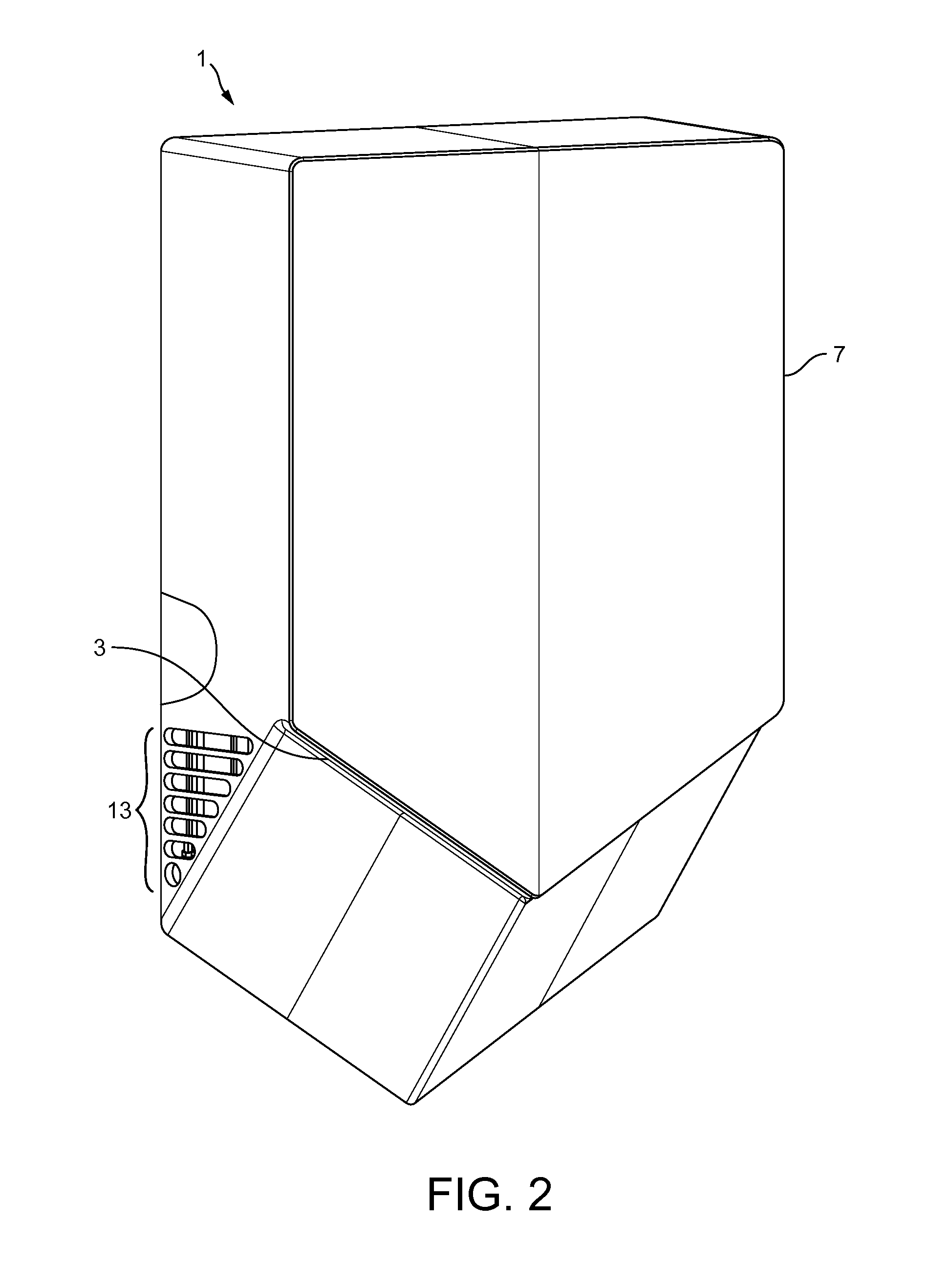
[0042]FIGS. 1-3 show a wall-mountable hand dryer 1 in accordance with the invention.

[0043]The hand dryer 1 discharges an airflow to dry the user's hands. The airflow is discharged at high speed (>80 m / s) through two air outlets 3, 5 on the hand dryer 1. Each outlet 3, 5 takes the form of an air-knife discharge outlet: in this case a narrow slit —less than 2 mm wide—which is machined directly into the external casing 7 of the hand dryer 1. The airflow is thus discharged as two thin, high velocity sheets of air (FIG. 3) or “air-knives”3a, 5a.

[0044]The mode of operation of the hand dryer 1 is analogous to the established use of air knives in industry to remove debris or liquid from the surface of a product (see e.g. EP2394123A1, which describes removal of debris from a glass sheet using air knives): each air-knife moves across the surface of a respective hand and, as it does so, wipes or scrapes the water from the surface of the hand.

[0045]The hands are inserted palm-open un...


PUM


Abstract

The present invention relates to a hand dryer for drying a user's hands by means of an airflow discharged through an air outlet on the hand dryer. The airflow is generated by a motor-driven fan unit, the airflow exiting the fan unit through a fan outlet on the fan unit. The fan unit is mounted to a fixed part of the hand dryer by means of an inflatable mount secured to the fixed part. The mount incorporates at least one inflatable duct connecting the fan outlet to the air outlet, which inflatable duct is, in use, inflated by the airflow passing from the fan outlet to the air outlet to provide pneumatic support for the fan unit.

Description

REFERENCE TO RELATED APPLICATIONS[0001]This application claims the priority of United Kingdom Application No. 1220893.0, filed Nov. 21, 2012, the entire contents of which are incorporated herein by reference.FIELD OF THE INVENTION[0002]The present invention relates to the field of hand dryers.BACKGROUND OF THE INVENTION[0003]There are various designs of hand dryer on the market, which are typically installed in public washrooms as an alternative to paper towels.[0004]Hand dryers rely on airflow to dry a user's hands. The airflow is typically discharged through one or more air outlets on the hand dryer and the user holds the hands in close proximity to the air outlet(s) so that the airflow is directed onto the user's hands to provide a drying effect.[0005]The principal drying mechanism may differ between different types of hand dryer. The drying mechanism may be evaporative, in which case the airflow will tend to be heated. Alternatively, the drying mechanism may rely mainly on a mom...

Claims


Application Information

Patent Timeline
IPC IPC(8): F26B21/00
CPCF26B21/004A47K10/48
Inventor TURRINI-ROCHFORD, TIMSTEELE, STUART JAMESCOURTNEY, STEPHEN BENJAMIN
Owner DYSON TECH LTD
Why Eureka
Try Eureka