
Vibration monitoring system

a technology of vibration monitoring and vibration sensor, applied in the direction of vibration measurement in solids, fluid pressure measurement by mechanical elements, blast furnaces, etc., can solve the problems of short system life, inability to operate or monitor continuously, and device not generating events

Inactive Publication Date: 2014-05-22
IBM CORP
View PDF9 Cites 12 Cited by
  • Summary
  • Abstract
  • Description
  • Claims
  • Application Information

AI Technical Summary

Benefits of technology

The patent describes a method for detecting the dominant frequency of a velocity frame by analyzing the frequency spectrum of each windowed velocity frame. This is done by using a real-value Bruun Fast Fourier Transform to search for the frequency index that maximizes the magnitude of the frequency spectrum. The technical effect of this invention is to provide a more accurate and efficient way to detect the dominant frequency of a velocity frame, which can be useful in various applications such as motion detection and video analysis.

Problems solved by technology

Other systems may be wireless, but often transmit their recorded data in bulk, requiring much bandwidth and transferring much information that is of no interest to the monitor, hence requiring considerable energy and thus resulting in a short system lifetime.
Those usually use microcontrollers for processing, which allow only a limited complexity of algorithms or require extended computation times, hence not allowing low-power operation or continuous monitoring.
However, these devices do not generate events, but rather describe distributed signal processing algorithms.
Additionally, they do not include special functionality for long-term monitoring of damage to buildings.

Method used


Image

  • Vibration monitoring system
  • Vibration monitoring system
  • Vibration monitoring system

Examples


Embodiment Construction

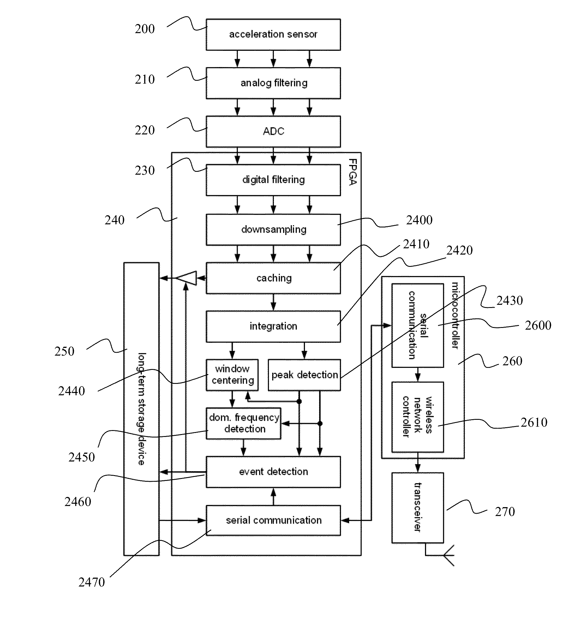
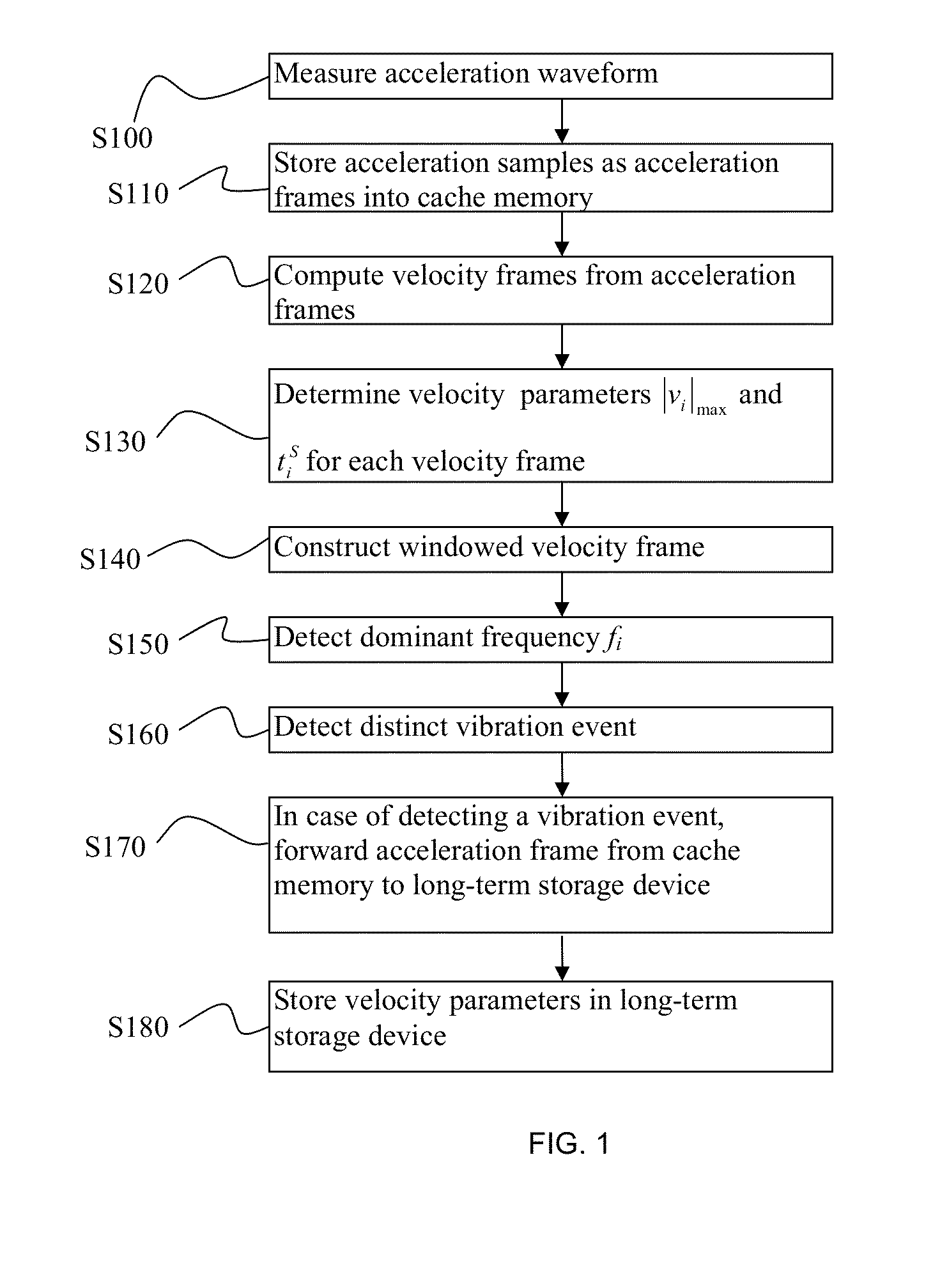
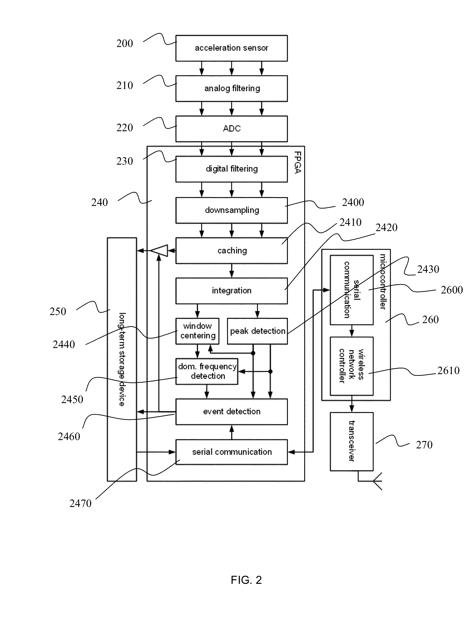
[0033]The invention describes a method for monitoring vibrations and detecting vibrations exceeding given thresholds, for example the ones stated in DIN 4150-3 for limits of vibration on building structures. A vibration is first transformed into an acceleration waveform that is then converted from an analog continuous quantity to a discrete time digital representation. These acceleration samples form acceleration frames from which a number of velocity parameters are determined. Acceleration frames are stored in a cache memory. A cache memory is a memory which serves as temporary storage. For each acceleration frame, the velocity parameters are saved to a long-term storage device, thus creating a continuous stream of velocity parameters. The method further compares the velocity parameters to a configurable threshold function, e.g. defined by DIN 4150-3. In case the threshold function is exceeded, the acceleration frame corresponding to the event is also forwarded to a long-term stora...


PUM

PropertyMeasurementUnit
cut-off frequencyaaaaaaaaaa

Abstract

The invention is directed to a method for monitoring vibrations to detect distinct vibration events in an acceleration waveform converted into acceleration samples. The method comprises: storing the acceleration samples as a sequence of acceleration frames into a cache memory (S110); detecting the presence or absence of a distinct vibration event in each of said acceleration frames (S160); in case of detecting a distinct vibration event in an acceleration frame, forwarding said acceleration frame from said cache memory to a long-term storage device (S170).

Description

FIELD OF THE INVENTION[0001]The invention relates to a method and device for measuring and digitally processing a vibration sensor signal. Especially, the invention is related to a low-power wireless vibration analysis sensor system to monitor for vibration damage to buildings according to DIN 4150-3.BACKGROUND[0002]The standard of the German Institute for Standardization DIN 4150-3 “Vibration in buildings—Part 3: Effects on structures” defines a method to measure and assess vibrations on buildings and recommends thresholds below which vibrations can be considered not harmful for different classes of buildings, such as industrial, residence, and old or bad structural states.[0003]Existing systems for this task usually consist of a data logger to which one or multiple sensing devices, usually geophones, are connected. This data logger may be used for measurements until the on-board memory is filled, upon which the measurement is terminated.[0004]Some data loggers have integrated func...

Claims


Application Information

Patent Timeline
Patent Type & Authority Applications(United States)
IPC IPC(8): G01N29/04G01H1/00
CPCG01H1/00G01N29/04G01M5/0066G01M7/022G01M7/025G05B23/0235G01V1/01
Inventor LOMBRISER, CLEMENSSCHOTT, WOLFGANG H.WEISS, BRAT E.
Owner IBM CORP
Learn More