
Fuel nozzle for use in a turbine engine and method of assembly

Active Publication Date: 2014-05-29
GENERAL ELECTRIC CO
View PDF34 Cites 5 Cited by
  • Summary
  • Abstract
  • Description
  • Claims
  • Application Information

AI Technical Summary

Benefits of technology

This patent describes a fuel nozzle for use in a turbine engine. The nozzle includes a fuel injector and a premixer tube, which is a long tube that receives the fuel and air and where they mix as they flow through the tube. The premixer tube is connected to the fuel injector in a way that allows for a continuous flow of fuel and air. The technical effect of this design is a more efficient mixing of the fuel and air, which leads to better combustion in the engine and improved performance overall. This patent also describes a method for assembling the fuel nozzle.

Problems solved by technology

Such engines may have high specific work and power per unit mass flow requirements.
Such emissions are generally undesirable and may be harmful to the environment.
However, SCR systems increase the overall costs associated with turbine operation.
However, the presence of water in the turbine engine may result in damage to engine components such as turbine blades and the combustion liner.

Method used


Image

  • Fuel nozzle for use in a turbine engine and method of assembly
  • Fuel nozzle for use in a turbine engine and method of assembly
  • Fuel nozzle for use in a turbine engine and method of assembly

Examples


Embodiment Construction

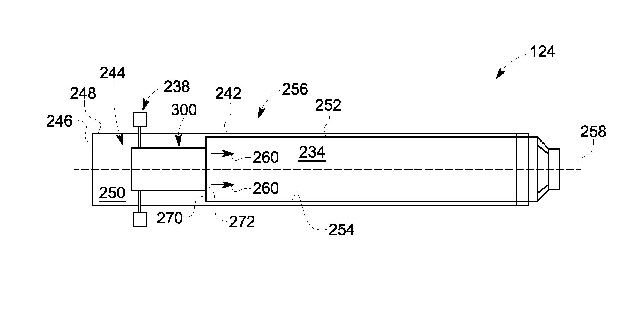
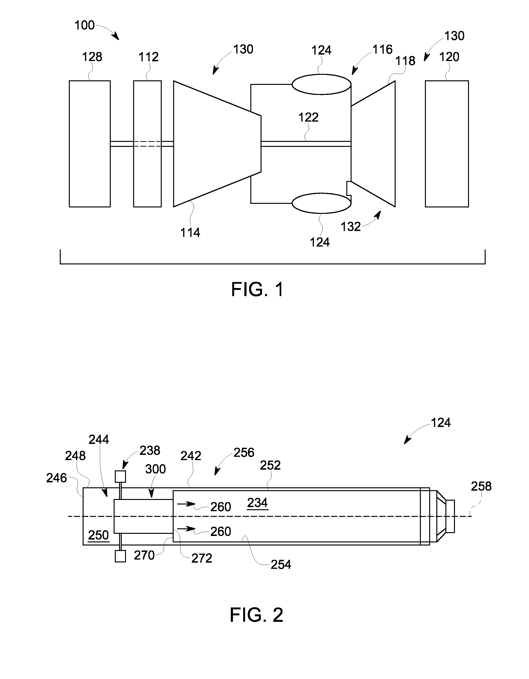
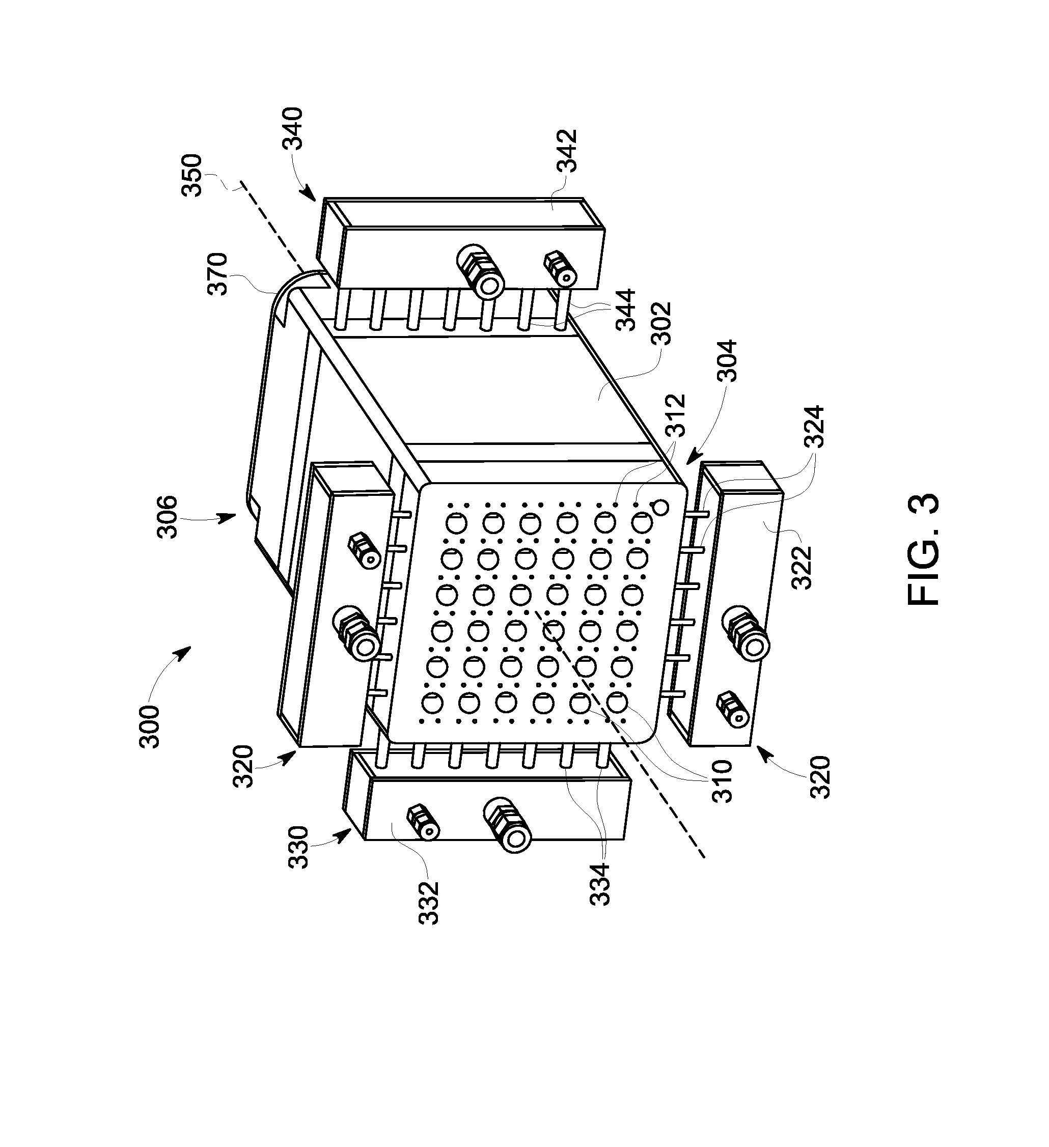
[0015]Embodiments of the present disclosure enable the use of liquid fuel in a gas turbine combustor with or without water injection while still achieving low NOx levels. In the exemplary embodiments, the combustor flame is stabilized based on a jet concept and not a swirl concept. More specifically, embodiments of the present disclosure pre-mix fuel and air in a fuel nozzle by pre-vaporizing liquid fuel in a flow of compressed air. Air is channeled from the compressor to the fuel nozzles while fuel injection spokes simultaneously inject liquid fuel into the fuel nozzles. The spokes include small injection ports defined therein such that the fuel injector described herein may be classified as a “plain orifice atomizer”. Plain orifice atomizers are known to be a cost efficient injector and are known to have a narrow jet angle, which facilitates minimizing the need to wet the fuel nozzle surfaces. Furthermore, by using a jet concept as opposed to a swirl concept, the likelihood of aut...


PUM


Abstract

A fuel nozzle for use in a turbine engine is provided. The fuel nozzle includes a fuel injector configured to discharge a flow of fuel therefrom and a premixer tube coupled in flow communication with the fuel injector. The premixer tube is configured to receive the fuel flow and a flow of air at an upstream end of the premixer tube, wherein the fuel and air are progressively mixed as the fuel and air are channeled through the length of the premixer tube.

Description

BACKGROUND OF THE INVENTION[0001]The field of the present disclosure relates generally to turbine engines and, more specifically, to a fuel nozzle for use in a turbine engine.[0002]Rotary machines, such as gas turbines, are often used to generate power for electric generators. Gas turbines, for example, have a gas path which typically includes, in serial-flow relationship, an air intake, a compressor, a combustor, a turbine, and a gas outlet. Compressor and turbine sections include at least one row of circumferentially-spaced rotating buckets or blades coupled within a housing. At least some known turbine engines are used in cogeneration facilities and power plants. Such engines may have high specific work and power per unit mass flow requirements. To increase operating efficiency, at least some known gas turbine engines may operate at increased combustion temperatures.[0003]While operating known turbine engines at higher temperatures increases operating efficiency, it may also incr...

Claims


Application Information

Patent Timeline
IPC IPC(8): F23R3/28
CPCF23R3/286F23D14/62F23D14/64
Inventor ABD EL-NABI, BASSAM SABRY MOHAMMADBOARDMAN, GREGORY ALLEN
Owner GENERAL ELECTRIC CO
Learn More