
Cooling system and device housing apparatus using the same

a technology of cooling system and device housing, applied in the field of cooling system, can solve the problems of increasing the load of air-conditioning equipment which controls the temperature of the server room, and achieve the effect of efficient heat exchange with the cooling obj

Active Publication Date: 2014-05-29
NEC CORP
View PDF3 Cites 15 Cited by
  • Summary
  • Abstract
  • Description
  • Claims
  • Application Information

AI Technical Summary

Benefits of technology

The invention allows for efficient heat exchange without the need for a compressor, which can make the process more cost-effective and reliable.

Problems solved by technology

However, by progress of consolidation of electronic devices along with increase of the information processing amount and increase of heat released from each electronic device, a load of air-conditioning equipment which controls the temperature of a server room is becoming large.

Method used


Image

  • Cooling system and device housing apparatus using the same
  • Cooling system and device housing apparatus using the same
  • Cooling system and device housing apparatus using the same

Examples


first exemplary embodiment

The First Exemplary Embodiment

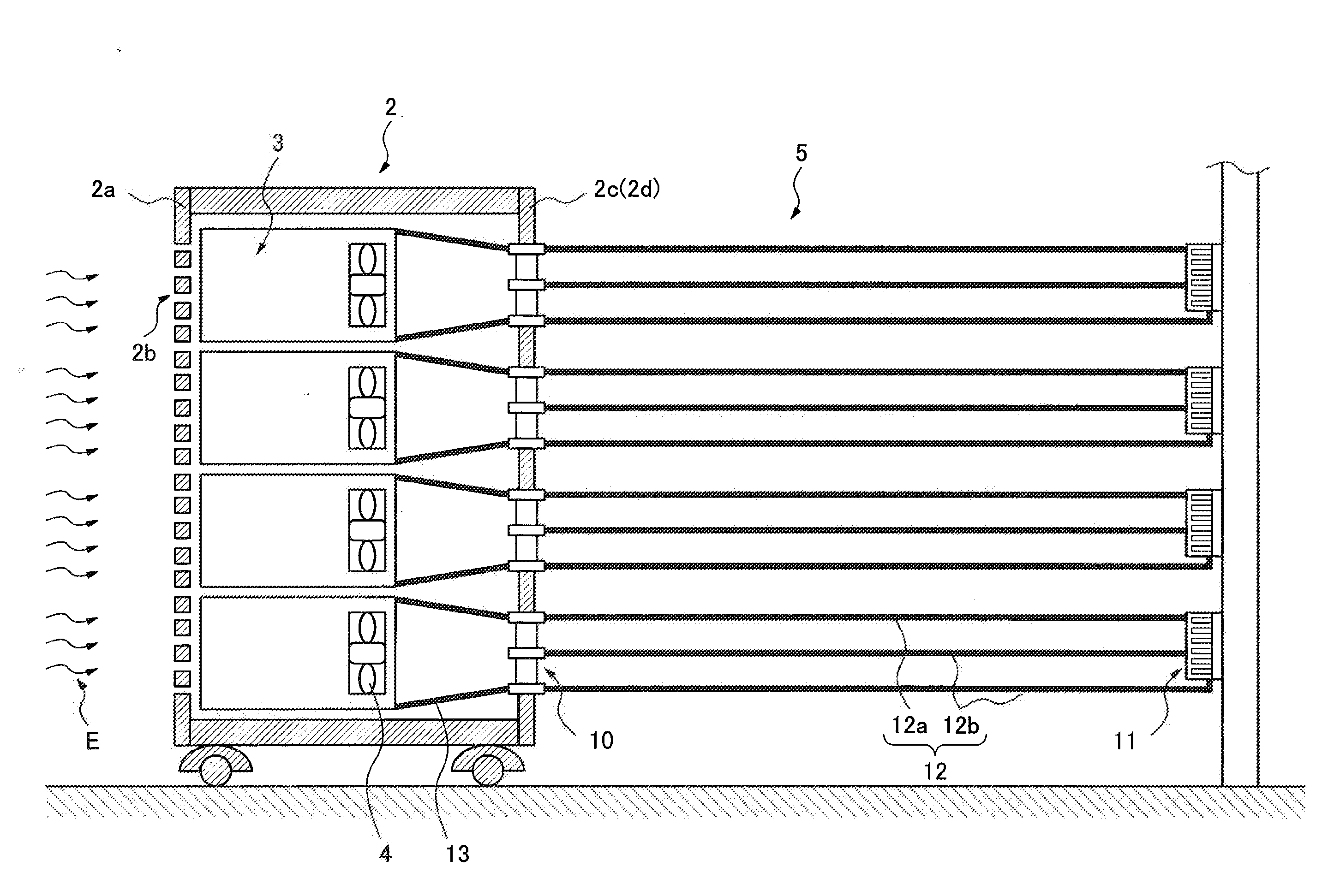
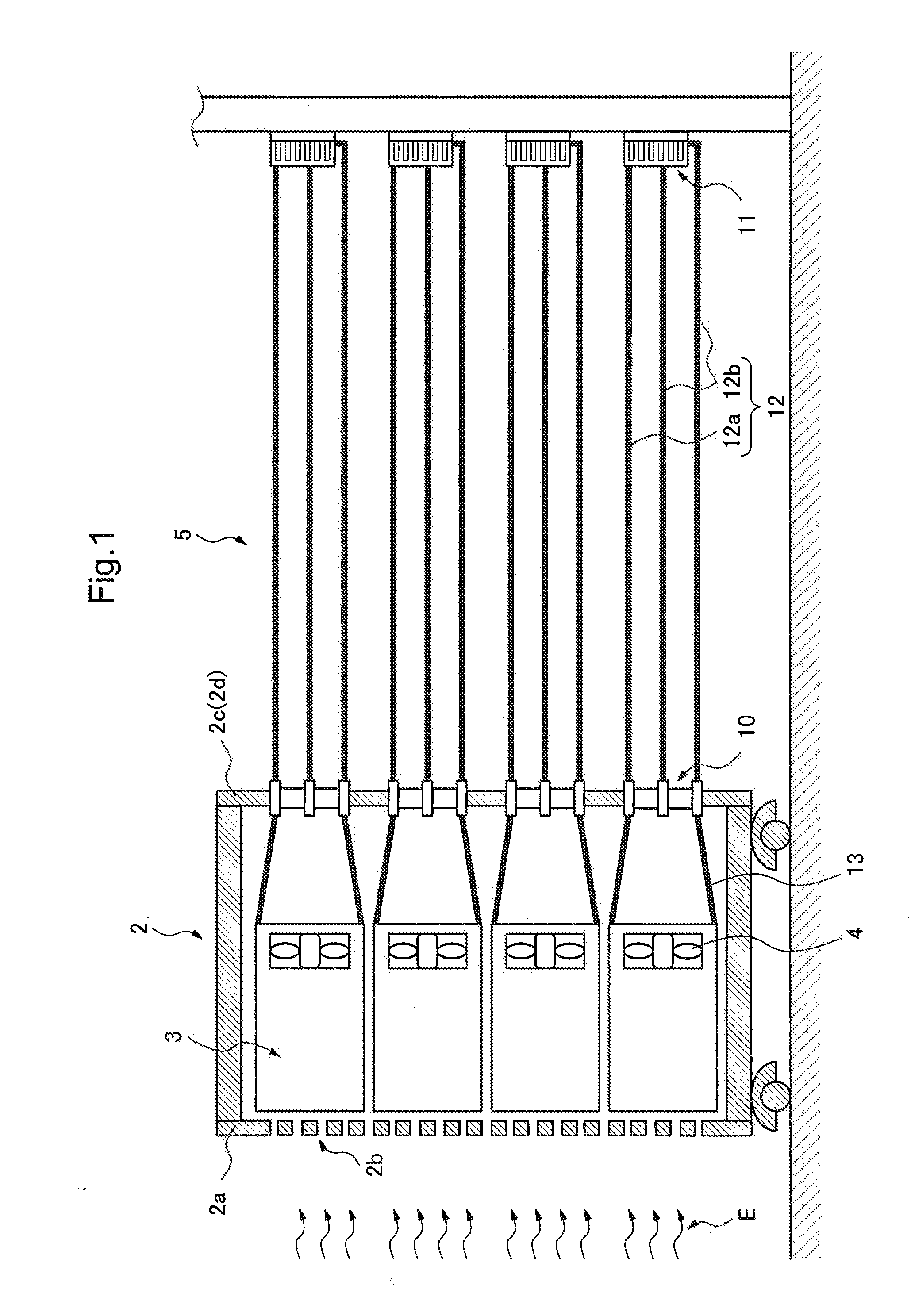
[0022]The first exemplary embodiment of the present invention will be described. FIG. 1 is a sectional side view of a device housing apparatus 2 having a cooling system 5 according to the first exemplary embodiment of the present invention. Meanwhile, because it is often the case that a plurality of pieces such device housing apparatus 2 are installed inside a building such as a machine room and a data center, description will be made assuming that the installation site of the device housing apparatus 2 is a machine room in the following description.

[0023]The device housing apparatus 2 is almost a box-like object having a rack structure or the like that stores a plurality of pieces of electronic device 3. There are provided a plurality of pieces of inlet 2b in a front plate 2a (the side plate in the left side in FIG. 1) of the device housing apparatus 2, and a rear door 2d is provided in a back plate 2c (the side plate in the right side in FIG. 1). FIG....

second exemplary embodiment

[0062]Next, the second exemplary embodiment of the present invention will be described. Meanwhile, about the same structures as the first exemplary embodiment, the description will be omitted appropriately using identical codes.

[0063]In the first exemplary embodiment, the inner walls of the first flow path, the second flow path and the third flow path are of a simple circularity or an ellipsoid. On the other hand, in this exemplary embodiment, there is provided a convex portion in an inner wall of the first flow path, the second flow path and the third flow path along the lengthwise direction.

[0064]FIG. 8 is a fragmentary perspective view of the upper part steam generating tube 23a having a convex portion 23c. As shown in this figure, the convex portion 23c is formed onto the inner walls of the first flow path 31a, the second flow path 31b and the third flow path 31c along a flow path. By this convex portion 23c, the heat exchanging efficiency between outside air and a refrigerant c...


PUM


Abstract

A cooling system comprising: an evaporator for evaporating a refrigerant by performing heat exchange with outside air; a condenser for condensing a gas refrigerant into a liquid refrigerant by making a refrigerant and a cooling medium perform heat exchange with each other; a gas refrigerant pipe and a liquid refrigerant pipe connecting the evaporator and the condenser; and the evaporator including: an upper part header provided in a highest position of the evaporator, and connected with the condenser by the gas refrigerant pipe, through the gas refrigerant pipe a gas refrigerant flowing; a lower part header provided in a lowest position of the evaporator, and connected with the condenser by the liquid refrigerant pipe, through the liquid refrigerant pipe a liquid refrigerant flowing; a middle header provided in an intermediate position between the upper part header and the lower part header, and connected with the condenser by the liquid refrigerant pipe, through the liquid refrigerant pipe the liquid refrigerant flowing; an upper part evaporator, arranged between the upper part header and the middle header, including an upper part steam generating tube having a first flow path for leading a refrigerant of the middle header to the upper part header while making the refrigerant of the middle header perform heat exchange with outside air and having a second flow path for leading a refrigerant of the lower part header to the upper part header while making the refrigerant of the lower part header perform heat exchange with outside air; and a lower part evaporator, arranged between the lower part header and the middle header, including a lower part steam generating tube having a third flow path inserted into the middle header while making a refrigerant of the lower part header perform heat exchange with outside air, the lower part steam generating tube communicated with the second flow path of the upper part steam generating tube.

Description

TECHNICAL FIELD[0001]The present invention relates to a cooling system for cooling electronic devices, and a device housing apparatus which is equipped with this cooling system and stores a plurality of electronic devices.BACKGROUND ART[0002]In recent years, the amount of information processing that is needed is increasing along with improvement of the information processing technology, development of the internet environment and the like. In such situation, data center business to install and operate electronic devices of such as a server for internet, data communication equipment, a fixed-line phone, a cellular phone and an IP telephone in a concentrated manner is being paid attention. Generally, a plurality of such electronic devices are housed in a rack or the like. Then, a plurality of such racks are installed in a server room.[0003]Meanwhile, by heat from electronic devices, a room temperature in a server room rises. Accordingly, air-conditioning equipment is installed usually...

Claims


Application Information

Patent Timeline
Patent Type & Authority Applications(United States)
IPC IPC(8): H05K7/20
CPCH05K7/20318H05K7/20309F28D15/0266G06F1/20G06F2200/201H05K7/20727H05K7/20818
Inventor INABA, KENICHIYOSHIKAWA, MINORUSAKAMOTO, HITOSHICHIBA, MASAKIMATSUNAGA, ARIHIRO
Owner NEC CORP
Features
  • Generate Ideas
  • Intellectual Property
  • Life Sciences
  • Materials
  • Tech Scout
  • Unparalleled Data Quality
  • Higher Quality Content
  • 60% Fewer Hallucinations
Learn More