Methods of Enhancing the Fracture Conductivity of Multiple Interval Fractures in Subterranean Formations Propped with Cement Packs

Inactive Publication Date: 2014-05-29
HALLIBURTON ENERGY SERVICES INC
View PDF12 Cites 22 Cited by
  • Summary
  • Abstract
  • Description
  • Claims
  • Application Information

AI Technical Summary

Benefits of technology

[0009]In one embodiment, the present invention provides a method comprising: providing a wellbore in a subterranean formation having a top portion and a bottom portion, and a middle portion therebetween; providing a jetting fluid comprising a base fluid and a cutting particulate; providing a cement slurry comprising an expandable cementitious material; providing a breakable gel fluid; introducing the jetting fluid into the bottom portion of the wellbore in the subterranean formation at a pressure sufficient to create or enhance a bottom portion fracture therein; introducing the jetting fluid into the top portion of the wellbore in the subterranean formation at a pressure sufficient to create or enhance a top portion fracture therein; introducing the cement slurry into the top portion fracture; introducing the cement slurry into the bottom portion fracture; introducing the breakable gel fluid into the wellbore in the subterranean formation so as to prevent the expandable cementitious material from migrating out of the top portion fracture and bottom portion fracture in the subterranean formation; curing the expandable cementitious material so as to form a cement pack, wherein the curing of the expandable cementitious material expands the expandable cementitious material such that at least one microfracture is created within top portion fracture and the bottom portion fracture in the subterranean formation; breaking the breakable gel fluid; and removing the broken breakable gel fluid from the subterranean formation.
[0010]In other embodiments, the present invention provides a method comprising: providing a wellbore in a subterranean formation having a top portion and a bottom portion, and a middle portion therebetween; providing a jetting fluid comprising a base fluid and a cutting particulate; providing a cement slurry comprising an expandable cementitious material; providing a breakable gel fluid; introducing the jetting fluid into the bottom portion of the wellbore in the subterranean formation at a pressure sufficient to create or enhance a bottom portion fracture therein; introducing the jetting fluid into the middle portion of the wellbore in the subterranean formation at a pressure sufficient to create or enhance a middle portion fracture therein; introducing the jetting fluid into the top portion of the wellbore in the subterranean formation at a pressure sufficient to create or enhance a top portion fracture therein; introducing the cement slurry into the top portion fracture; introducing the cement slurr

Problems solved by technology

Thus, the fracture porosity is closely related to the strength of the placed proppant and tight proppant packs are often unable to produce highly conductive channels within a fracture, while a reduced volume of proppant is unable to withstand fracture closure.
Moreover, hydraulic fracturing in soft rock formations, such as carbonate formations, is often inadequate to create conductive pathways because the proppant and carbonate formation together are unable to withstand closure pressure.
The substantial volume of aqueous fluid introduced into a formation during traditional fracturing treatments may also result in dilution of later-placed treatment fluids, impairment of produced fluid flow due to formation fluid retention, or damaged formation portions causing reduced hydrocarbon permeability due to fluid-induced swelling of the formation.
Additionally, traditional hydraulic fracturing treatments alone may create only shallow fractures near the wellbore head, substantially impairing the conductivity potential of a subterranean formation as a whole.
However, such degradable particulat

Method used


Image

  • Methods of Enhancing the Fracture Conductivity of Multiple Interval Fractures in Subterranean Formations Propped with Cement Packs
  • Methods of Enhancing the Fracture Conductivity of Multiple Interval Fractures in Subterranean Formations Propped with Cement Packs
  • Methods of Enhancing the Fracture Conductivity of Multiple Interval Fractures in Subterranean Formations Propped with Cement Packs

Examples


Embodiment Construction

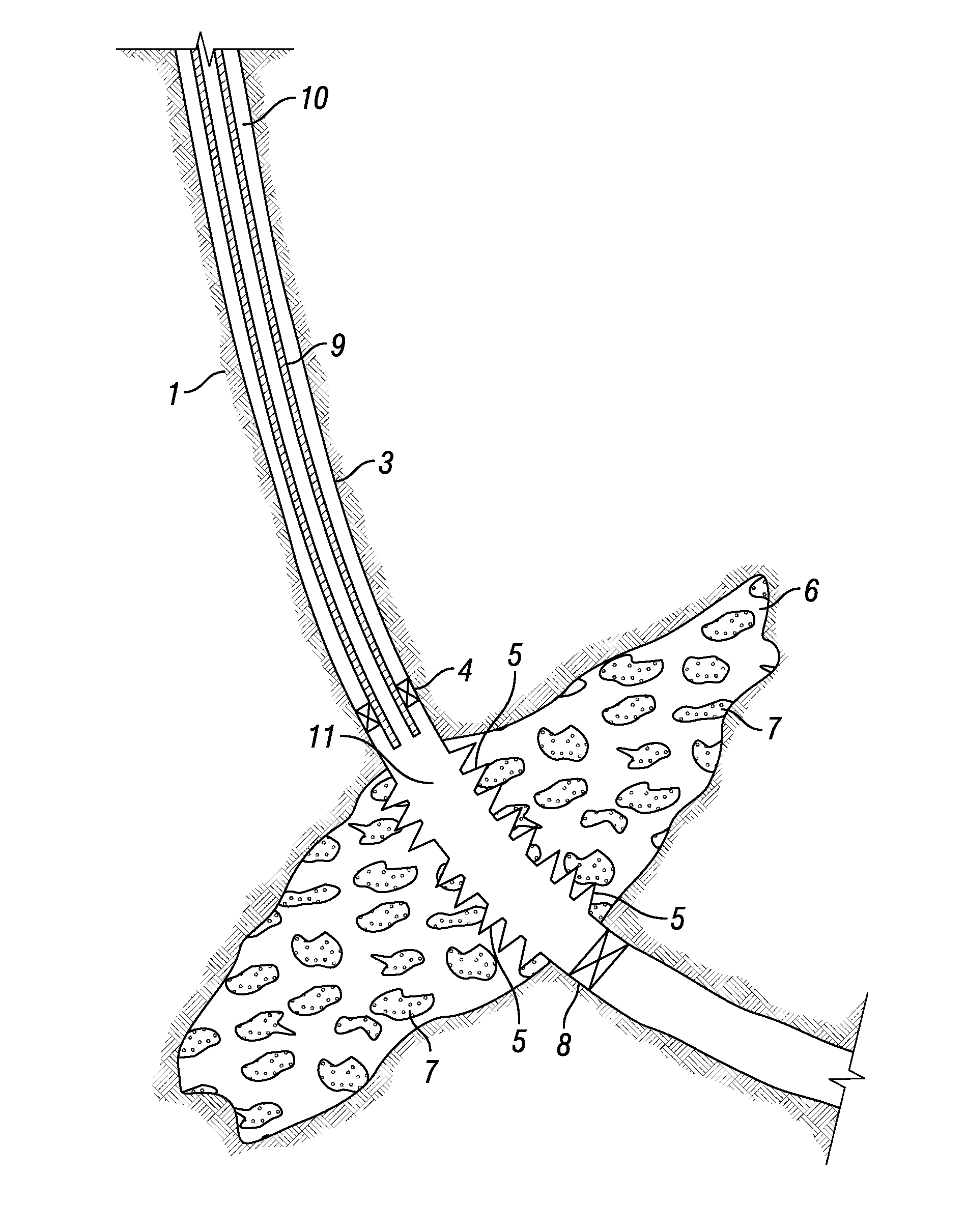
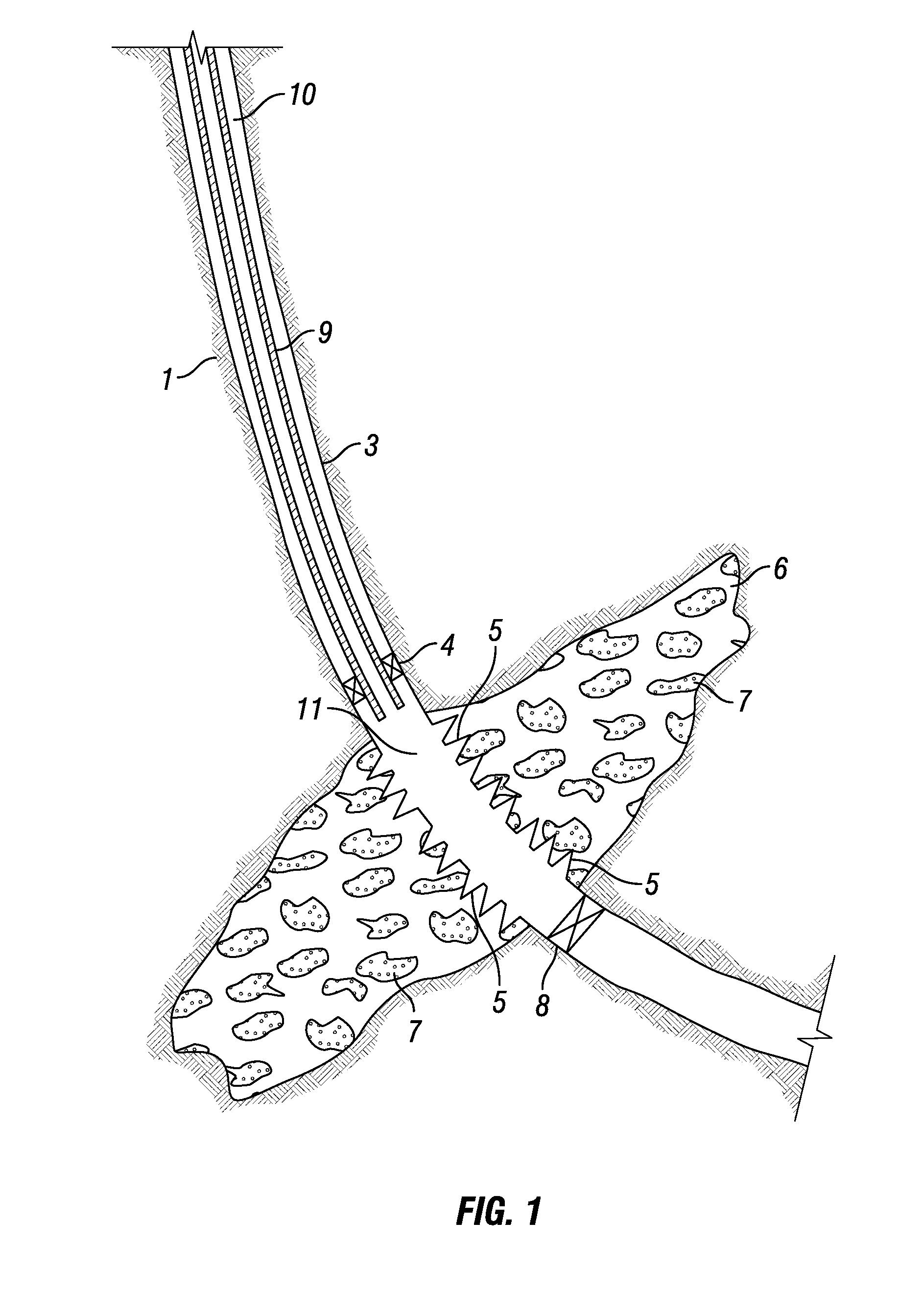
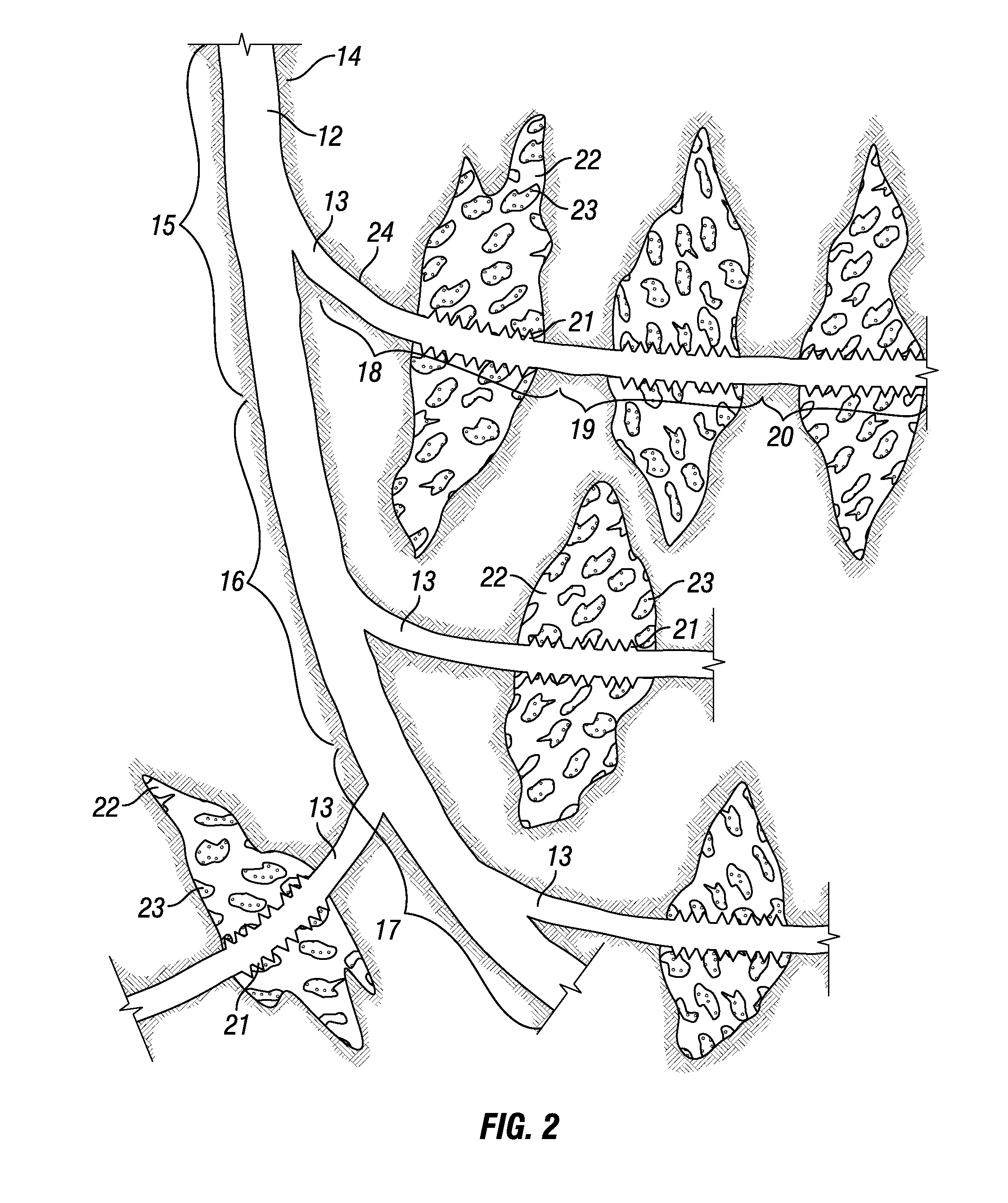
[0016]The present invention provides methods of enhancing fracture conductivity within propped subterranean formations using a cementitious material and methods of delivering and / or treating such cementitious material. The cementitious material of the present invention may be introduced alone as a “cement pack” within a fracture in a wellbore in a subterranean formation as a cementitious slurry that largely fills the interior of a fracture or a portion of the interior of a fracture (e.g., the cementitious material is packed into the fracture without spacer fluid to form). In other embodiments, the cementitious material of the present invention may be introduced in the form of cementitious material aggregates or cement pillars within a fracture in a subterranean formation. As used herein, the term “cementitious material aggregates” and related terms such as “cement pillars” refer to coherent cluster of wetted, settable cementitious material that remains a coherent body when placed in...


PUM


Abstract

Methods of treating a wellbore in a subterranean formation having a top portion and a bottom portion, and a middle portion therebetween. The method includes providing a jetting fluid; providing a cement slurry; and providing a breakable gel fluid. Then introducing the jetting fluid into the bottom portion of the wellbore to create or enhance a bottom portion fracture; introducing the jetting fluid into the top portion of the wellbore to create or enhance a top portion fracture; introducing the cement slurry into the top portion fracture; introducing the cement slurry into the bottom portion fracture; and introducing the breakable gel fluid into the wellbore so as to prevent the expandable cementitious material from migrating out of the top portion fracture and bottom portion fracture. The expandable cementitious material is cured so as to form a cement pack, the breakable gel fluid is broken and removed from the subterranean formation.

Description

BACKGROUND[0001]The present invention provides methods of enhancing fracture conductivity within propped subterranean formations using a cementitious material and methods of delivering and / or treating such cementitious material.[0002]Subterranean wells (e.g., hydrocarbon producing wells, water producing wells, and injection wells) are often stimulated by hydraulic fracturing treatments. In hydraulic fracturing treatments, a viscous treatment fluid is pumped into a portion of a subterranean formation at a rate and pressure such that the subterranean formation breaks down and one or more fractures are formed. While the treatment fluid used to initiate the fracture is generally solids-free, typically, particulate solids, such as graded sand, are suspended in a later portion of the treatment fluid and then deposited into the fractures. These particulate solids, or “proppants,” serve to prop the fracture open (e.g., keep the fracture from fully closing) after the hydraulic pressure is re...

Claims


Application Information

Patent Timeline
IPC IPC(8): E21B43/26
CPCE21B43/261
Inventor NGUYEN, PHILIP D.WEAVER, JIMMIE D.SANDERS, MICHAEL W.BRYANT, JASON E.EAST, LOYD E.IZQUIERDO, GUILLERMO ANTONIOSIERRA, LEOPOLDOHUNTER, TIMOTHY H.
Owner HALLIBURTON ENERGY SERVICES INC
Why Eureka
Try Eureka