RF coupler stabilization in an induction RF fluorescent light bulb

a technology of induction lamp and position stabilization, which is applied in the field of induction lamps, can solve the problems of not always a good fit for replacing conventional incandescent lamps, long lamps, and thin lamps, and achieve the effects of increasing the positional stabilization of rf couplers, reducing rattle and potential damage, and increasing structural suppor

Active Publication Date: 2014-05-29
LUCIDITY LIGHTS
View PDF5 Cites 23 Cited by
  • Summary
  • Abstract
  • Description
  • Claims
  • Application Information

AI Technical Summary

Benefits of technology

[0019]The present disclosure depicts an induction lamp with structures that increase RF coupler positional stabilization. These structures are capable of providing increased structural support and axial alignment for a power coupler located in a re-entrant cavity of a lamp envelope of the induction RF fluorescent light lamp, the re-entrant cavity having an open entrance end and a closed innermost end, and a pliable spacer positioned between and in contact with both the innermost end of the power coupler and the innermost end of the re-entrant cavity, the pliable ...

Problems solved by technology

Use of electrodes creates certain problems.
In the case of fluorescent lamps, this may lead to long, thin lamps, which function well for lighting office ceilings, but are not always a good fit for replacing conventional incandescent lamps.
A plastic cover shaped like a conventional incandescent lamp is sometimes placed over the bent tubes to provide a more attractive shape, but these covers absorb light, making the lamp less efficient.
Bent and spiral tube lamps also have wasted space between the tubes, making them larger than necessary.
The use of electrodes creates problems other than shape and size.
Electrodes can wear out if the lamp is turned on and off many times, as is typical in a residential bathroom and many other applications.
In addition, the long thin shape selected, because it is adapted to allow use of electrodes, tends to require time for mercury vapor to diffuse from one part of the tube to another, leading to the long warm-up times typically associated with many compact fluorescent lamps.
While ...

Method used


Image

  • RF coupler stabilization in an induction RF fluorescent light bulb
  • RF coupler stabilization in an induction RF fluorescent light bulb
  • RF coupler stabilization in an induction RF fluorescent light bulb

Examples


Embodiment Construction

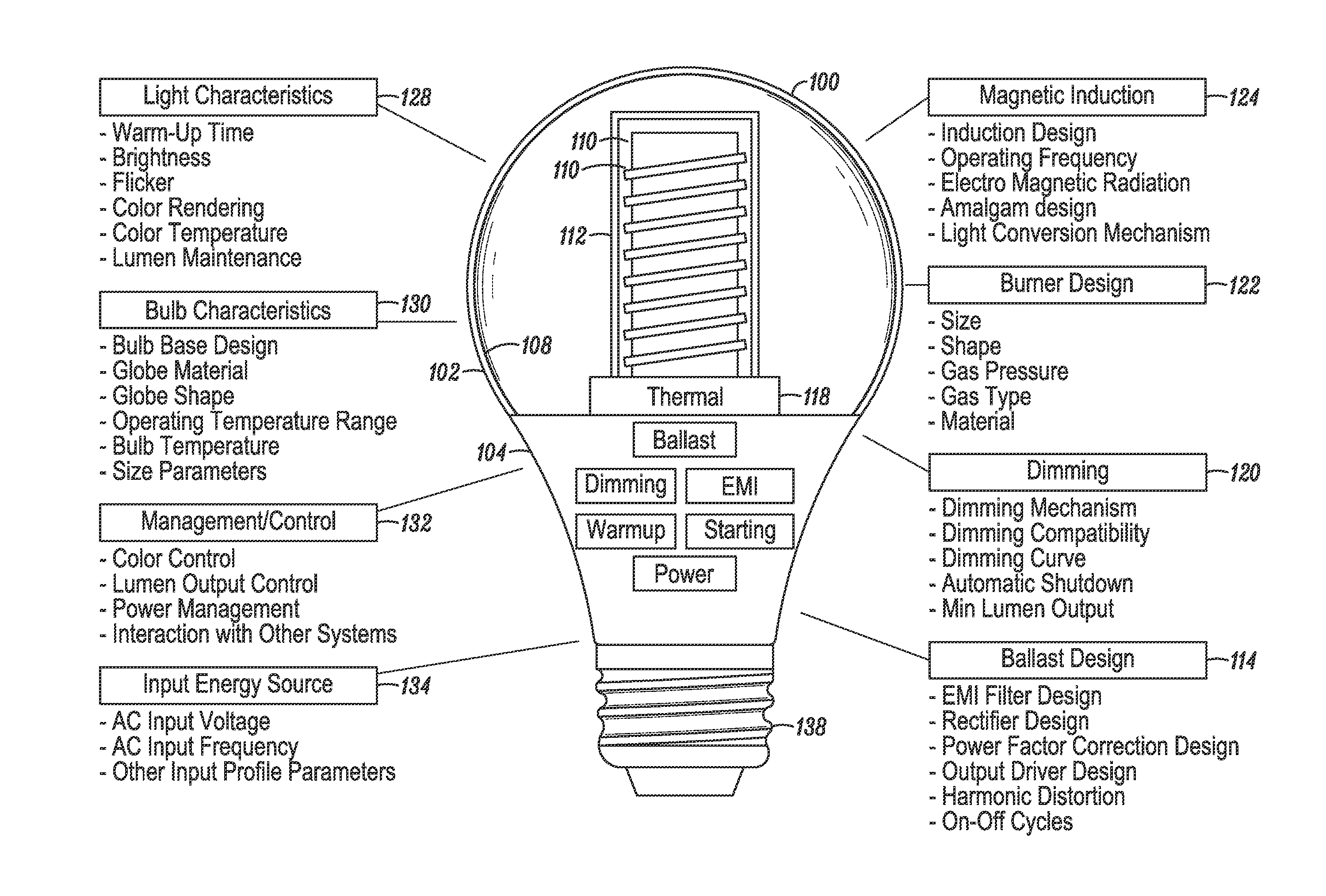
[0047]An induction-driven electrodeless discharge lamp, hereafter referred to synonymously as an induction lamp, an electrodeless lamp, or an electrodeless fluorescent lamp, excites a gas within a lamp envelope through an electric field created by a time-varying magnetic field rather than through electrically conductive connections (such as electrodes) that physically protrude into the envelope. Since the electrodes are a limiting factor in the life of a lamp, eliminating them potentially extends the life that may be expected from the light source. In addition, because there are no metallic electrodes within the envelope, the burner design may employ high efficiency materials that would otherwise react with the electrodes, such as bromine, chlorine, iodine, and the like, and mixtures thereof, such as sodium iodide and cerium chloride. Embodiments described herein disclose an inductor mounted inside a re-entrant cavity protruding upward within the burner envelope, where the inductor ...


PUM


Abstract

An induction RF fluorescent light lamp capable of providing increased structural support and axial alignment for a power coupler located in a re-entrant cavity of a lamp envelope of the induction RF fluorescent light lamp, the lamp envelope with re-entrant cavity both covered on a partial vacuum side with phosphor and filled with a working gas mixture, the re-entrant cavity having an open entrance end and a closed innermost end, and a pliable spacer positioned between and in contact with both the innermost end of the power coupler and the innermost end of the re-entrant cavity, the pliable spacer having a shape that both provides structural support to prevent movement of the power coupler with respect to the re-entrant cavity and to provide axial alignment of the power coupler to the re-entrant cavity.

Description

CROSS-REFERENCE TO RELATED APPLICATIONS[0001]This application is a continuation-in-part of the following U.S. patent application, which is hereby incorporated by reference in its entirety: U.S. patent application Ser. No. 13 / 837,034 filed Mar. 15, 2013.[0002]The application Ser. No. 13 / 837,034 is a continuation-in-part of the following U.S. patent applications, each of which is hereby incorporated by reference in its entirety: U.S. patent application Ser. No. 13 / 684,660 filed Nov. 26, 2012, U.S. patent application Ser. No. 13 / 684,664 filed Nov. 26, 2012, and Ser. No. 13 / 684,665 filed Nov. 26, 2012.BACKGROUND[0003]1. Field[0004]The present invention generally relates to induction lamps, and more specifically to increasing RF coupler positional stabilization in an induction lamp.[0005]2. Description of Related Art[0006]Discharge lamps create light by exciting an electrical discharge in a gas and using that discharge to create visible light in various ways. In the case of fluorescent l...

Claims


Application Information

Patent Timeline
IPC IPC(8): H01J65/04
CPCH01J65/042H01J65/048H05B41/2806Y02B20/00
Inventor GODYAK, VALERY A.MAYA, JAKOB
Owner LUCIDITY LIGHTS
Why Eureka
Try Eureka