
Detachable electrode and anchor

a technology of electrodes and anchors, applied in the field of implantable medical devices, can solve the problems of removing electrodes, affecting the internal workings, and damage to the tissue where the electrode leads are attached, so as to minimize the chance of internal bleeding and minimize the impact on the vein

Active Publication Date: 2014-05-29
BIOTRONIK SE & CO KG
View PDF7 Cites 93 Cited by
  • Summary
  • Abstract
  • Description
  • Claims
  • Application Information

AI Technical Summary

Benefits of technology

This patent describes a detachable electrode and anchor that allows for easy removal and replacement of the electrode without leaving the anchor in place. The electrode has a conductive outer surface and insulative portions between them and is connected to a detachable anchor through a wire. The anchor can be made from a variety of materials and can be flexible or rigid depending on the intended application. This invention minimizes the chance of internal bleeding and impact on the vein in which the electrode travels. No need for larger diameter sheath is required for removing the electrode and attached anchor.

Problems solved by technology

Leaving unused electrode leads in place is suboptimal in that the unused leads may interfere with the internal workings of the veins or portion of the heart in which they remain.
Alternatively, removing the electrode lead may damage the tissue where the electrode lead is attached.
The main problem with this technique is that the extraction site is subject to internal bleeding.

Method used


Image

  • Detachable electrode and anchor
  • Detachable electrode and anchor
  • Detachable electrode and anchor

Examples


first embodiment

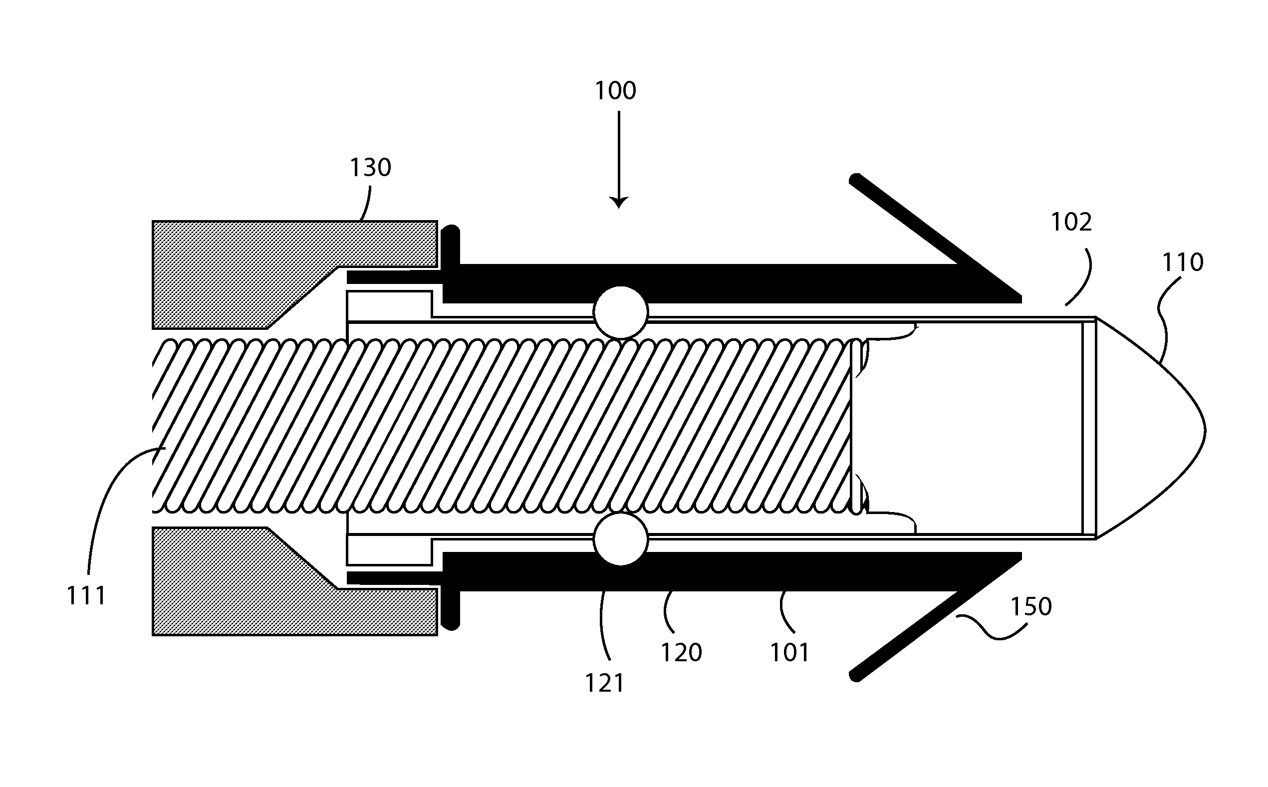
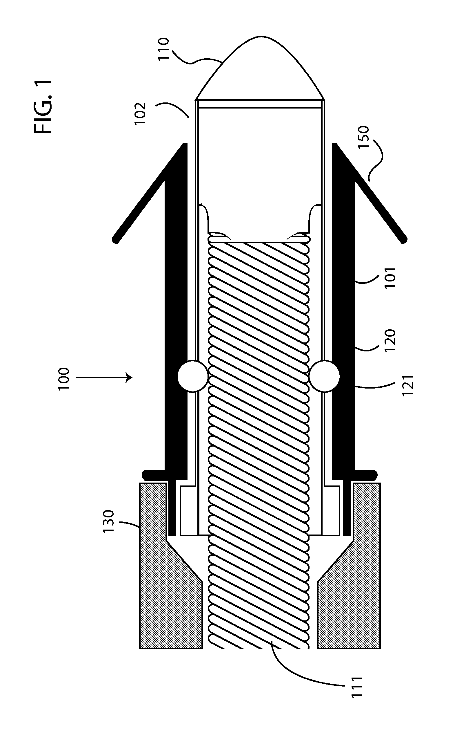
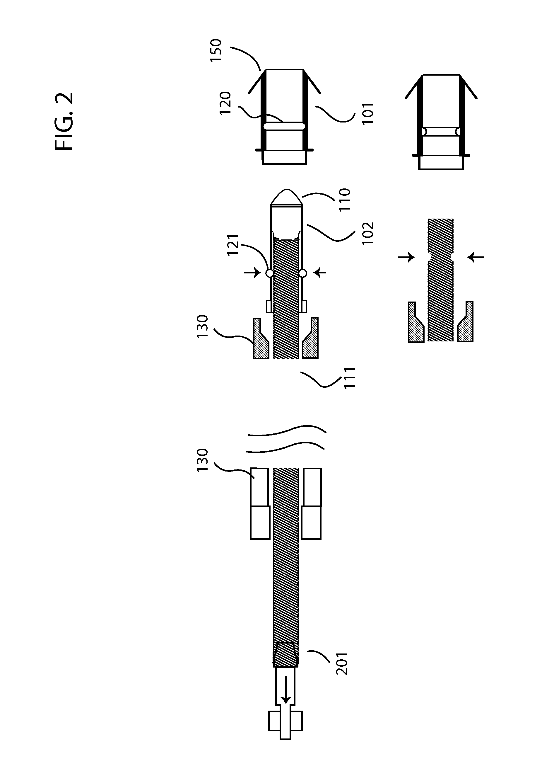
[0019]FIG. 1 shows a side view of the invention in the attached state that includes anchor 101 and a detachable electrode 102, which may be an electrode lead or a leadless medical implant. The electrode lead is shown as a coiled wire, while the leadless device is not shown for brevity, but rather excludes the coiled wire for example. All examples given with respect to an electrode lead may be applied equally to a leadless medical implant, such as a leadless pacemaker, drug reservoir, drug pump or any other type of leadless medical implant. Although many examples are given with respect to electrode leads, this does not limit the use of the apparatus described herein to electrode leads, but is described with respect to electrode leads for brevity.

[0020]In one or more embodiments, the electrode lead embodiment includes an electrode, such as tip electrode 110, insulating electrode body 130 and at least one electrically conductive wire 111 internally situated within the electrode lead an...

second embodiment

[0029]FIG. 3 shows a side view of the invention in the attached state. In this embodiment, the first detachable element in the electrode lead may include a first threaded element 121a and the second detachable element 120a in the anchor may include a second threaded element capable of rotationally engaging the first threaded element. This embodiment allows for rotational forces at the end of the electrode lead to disengage the electrode lead from the anchor. Leadless devices may also include hex nuts or facets in any number or spanner type coupling elements or slots or any other geometric shape that allows for rotational forces to be applied to couple the leadless device to the anchor as one skilled in the art will recognize.

[0030]FIG. 4 shows a side view of a second embodiment of the invention in the detached state. Although the attachment mechanism 150 is shown as rearward oriented tines, the attachment mechanism may also include a helix 160, for example of the opposing rotational...


PUM


Abstract

A detachable electrode and anchor utilized with electrode leads and leadless medical implants that enable explantation of the electrode while leaving the anchor in place. The detachable electrode and anchor utilizes a detachable mechanism that detachably couples the electrode to the anchor. Embodiments do not require removal of existing scar tissue before explantation, which minimize chances of internal bleeding at the extraction site. Embodiments also minimize impact on the vein in which the electrode lead travels by eliminating use of a necessarily larger diameter sheath that is utilized around the electrode lead to remove the electrode lead and attached anchor.

Description

[0001]This application claims the benefit of U.S. Provisional Patent Application 61 / 730,064, filed on 27 Nov. 2012, the specification of which is hereby incorporated herein by reference.BACKGROUND OF THE INVENTION[0002]1. Field of the Invention[0003]At least one embodiment of the invention generally relates to implantable medical devices that may later be detached and which may include electrodes, including electrode leads and leadless medical implants having at least one electrode and more particularly, but not by way of limitation, embodiments of the invention relate to a detachable electrode and anchor that may be detachably released from one another to explant the electrode and associated lead or leadless implant.[0004]2. Description of the Related Art[0005]Electrodes in the form of electrode leads or leadless medical implants are commonly implanted in patients in need of cardiac monitoring and if necessary, electrical stimulation. Electrical energy is sensed over the electrodes...

Claims


Application Information

Patent Timeline
IPC IPC(8): A61N1/05A61B5/042
CPCA61B5/042A61N1/059A61N1/37518A61N1/3756A61N1/37205A61N1/057
Inventor NORDSTROM, KARLAYTON, MICHAEL J.WENZEL, MATTHIAS
Owner BIOTRONIK SE & CO KG
Learn More