Gear with vibration sensor

Inactive Publication Date: 2014-06-05
AB SKF
View PDF8 Cites 5 Cited by
  • Summary
  • Abstract
  • Description
  • Claims
  • Application Information

AI Technical Summary

Benefits of technology

[0007]Preferably, the cavity is filled with potting material for sealing the vibration sensor. The potting material protects the electronics in the vibration sensor from e

Problems solved by technology

Furthermore, metal particles in the lubricant cannot touch the vibration sensor attachment which would lead to failure of the electronics.
If the vibration sensor were comprised in a vibration sensor

Method used


Image

  • Gear with vibration sensor
  • Gear with vibration sensor
  • Gear with vibration sensor

Examples


Embodiment Construction

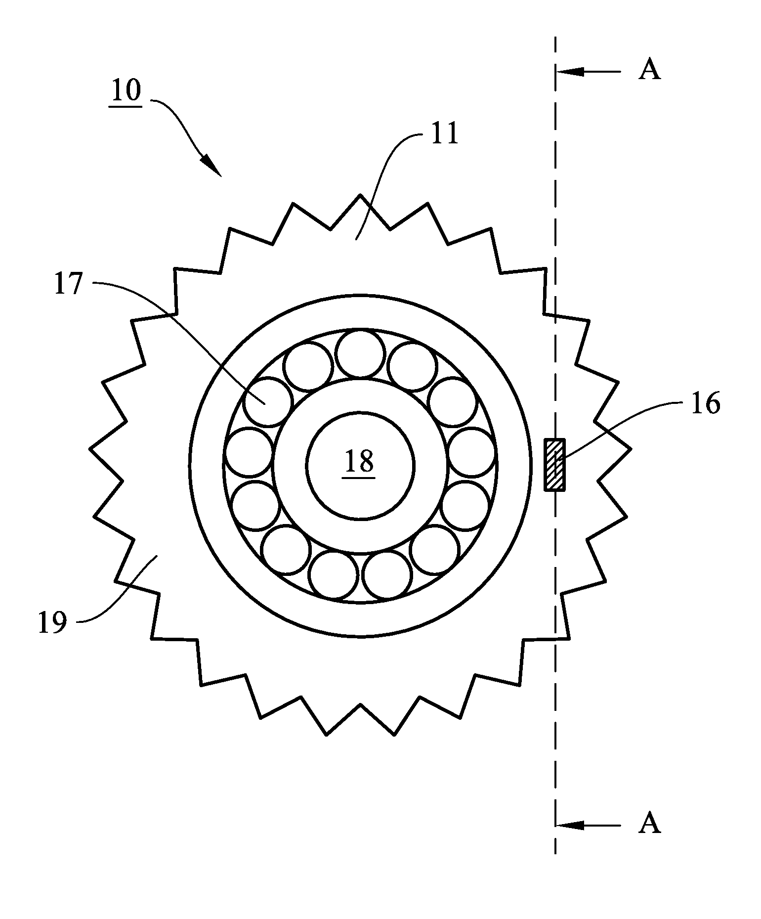
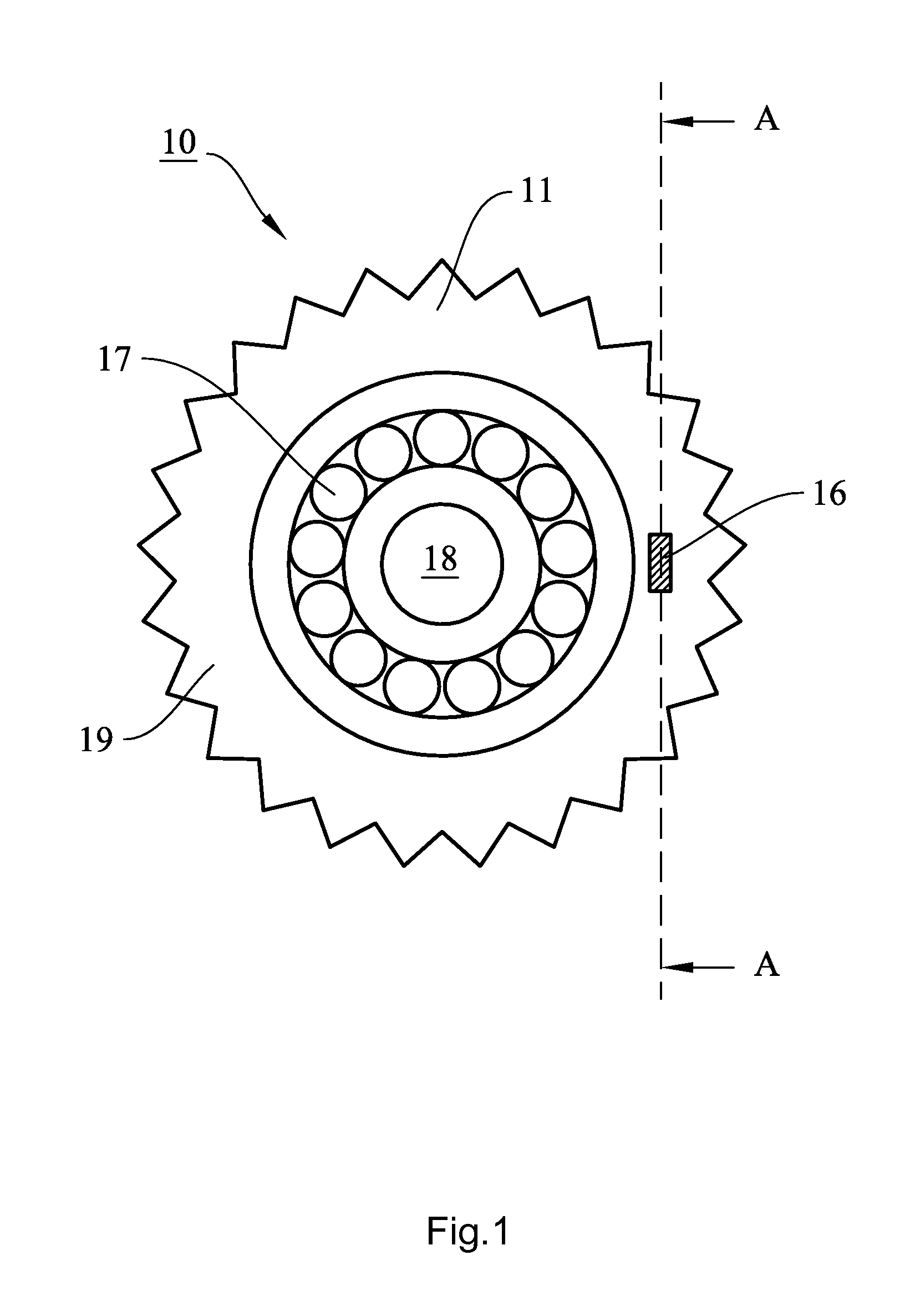
[0014]FIG. 1 shows a front view of the gear 10 and a planar gear surface 11 according to the invention. The gear surface 11 is coupled to a gear shaft 18 via bearings 17 enabling the gear surface 11 to rotate with respect to the gear shaft 18. The invention is however not limited to this specific gear arrangement. The invention can be used for measuring vibrations in any gear in any type of gear arrangement. For example, the invention may be used in one or more gear surfaces 11 of the planet gears in an epicyclic gear box. At a radially outer edge of the gear surface 11, gear teeth 19 for meshing with another gear are provided. The gear surface 11 further comprises a cavity 16 wherein a vibration sensor is embedded. Integrating the vibration sensor in the gear surface 11 enables direct measurement of vibrations of the gear with little interference of nearby vibration sources. The vibration sensor is described in detail below with reference to FIG. 3.

[0015]The gear 10 may be part of ...


PUM


Abstract

A gear is provided that includes a gear surface with a vibration sensor. The vibration sensor further includes an accelerometer coupled to a data transmitter and the vibration sensor is provided within a cavity in the gear surface.

Description

FIELD OF THE INVENTION [0001]This invention relates to a gear with a vibration sensor, the vibration sensor comprising an accelerometer coupled to a data transmitter.BACKGROUND OF THE INVENTION[0002]In e.g. wind turbines, it is important to monitor vibrations of the gears. Monitoring vibrations makes it possible to detect e.g. wear and micro-pitting before it causes serious malfunctioning of the turbine, and to initiate preventive or corrective maintenance before any major damage occurs. Usually, the gears are comprised in a gear box to which the vibration sensor is attached. A problem of this configuration is that the distance between the vibration sensor and the gears rotating in the gear box makes it difficult to pick up or identify the significant vibration frequencies. Additionally, the vibration signal in such a configuration is inherently noisy because of vibration in other gear box components.[0003]In the international patent application WO 2007 / 085259, a wind turbine with a...

Claims


Application Information

Patent Timeline
IPC IPC(8): F16H55/17
CPCF16H55/17F03D15/00F05B2260/4031F05B2260/96F16H2057/012Y02E10/72Y10T74/1987
Inventor CHRISTIANSSON, GORANZIEGLER, SEBASTIAN
Owner AB SKF
Why Eureka
Try Eureka