

Solar cell coating
a solar cell and membrane technology, applied in the direction of solar ray transmission, solar ray transmission, heat collector mounting/support, etc., can solve the problem of degrading the efficiency of solar modules
- Summary
- Abstract
- Description
- Claims
- Application Information
AI Technical Summary
Benefits of technology
Problems solved by technology
Method used
Image

Examples
Embodiment Construction
[0001]1. Field of the Invention
[0002]The present disclosure relates to hydrophobic coatings for solar cell modules.
[0003]2. Background of the Invention
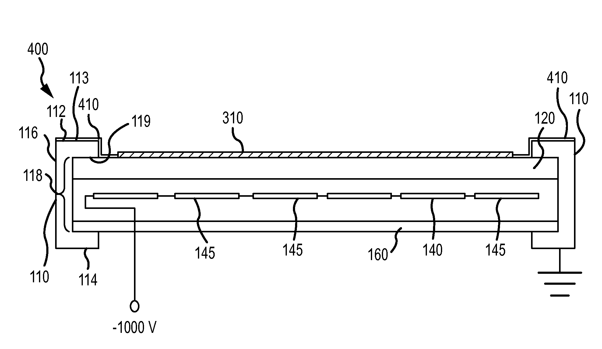
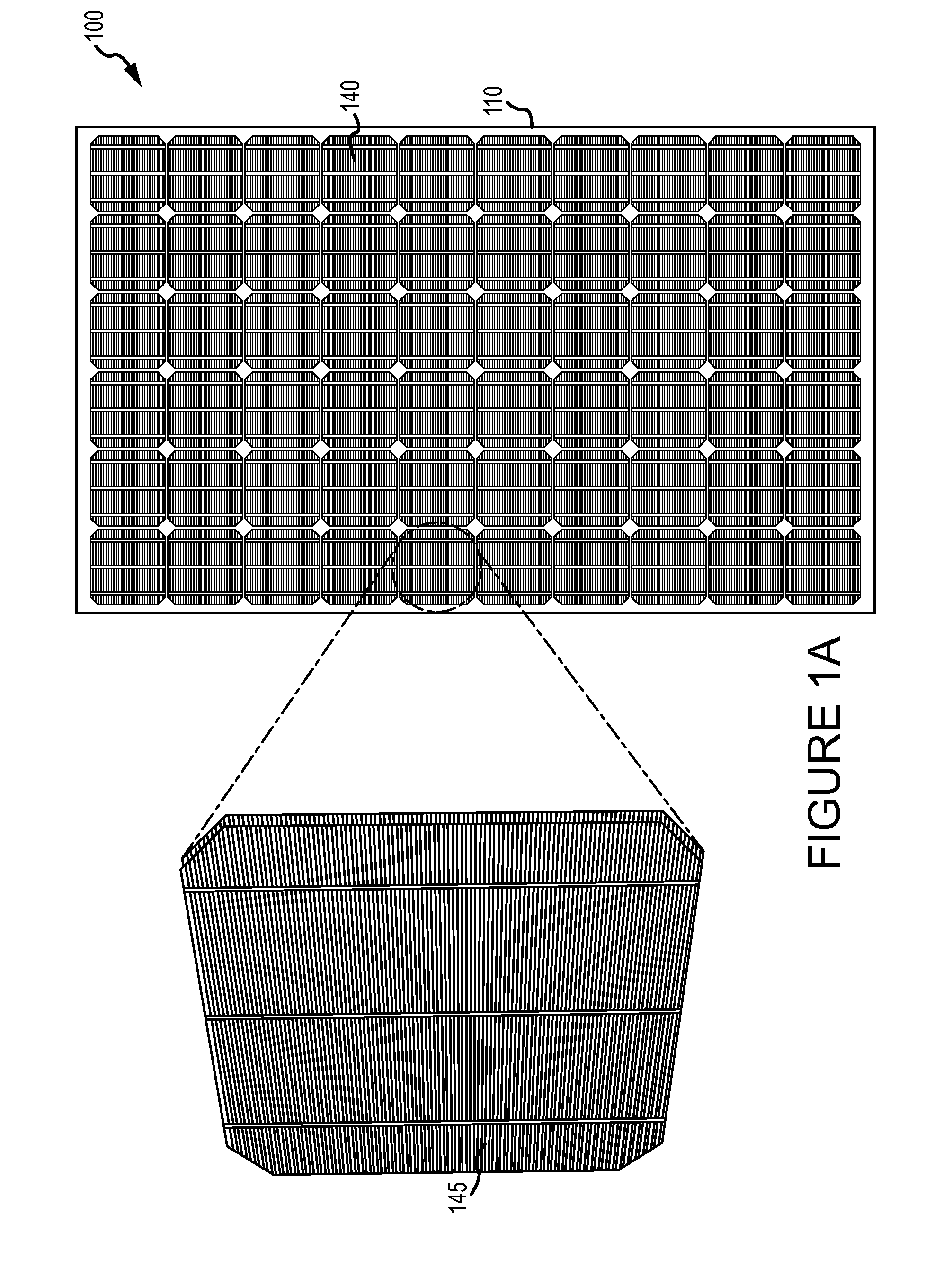
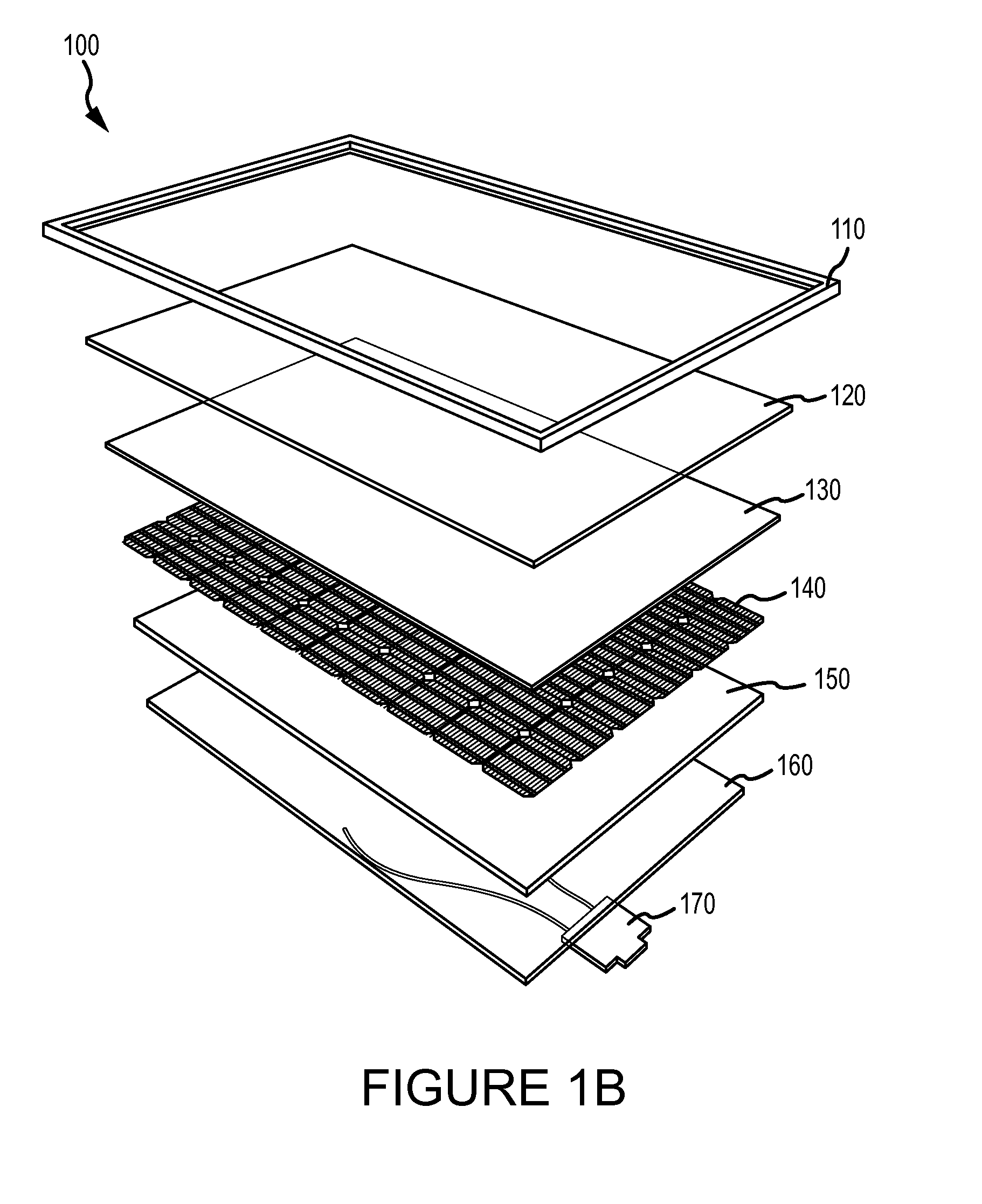
[0004]Solar cells (also known as photovoltaic cells) convert light energy into electricity. In many applications, solar cells are grouped together into modules to produce different voltage outputs. For example, some modules include 72 individual cells (in a 6×12 matrix) with each cell producing about 0.6V for a total output of about 40V per module. Other modules may include more or fewer cells and / or may produce more or less voltage. Such modules are often held together by a metallic (e.g., aluminum) frame and covered by a sheet of glass to protect the cells from water and debris. The frame is typically grounded for safety purposes. Some solar power-generation systems typically include about 25 modules which are connected in series. The cells in the far end module of such systems may reach a potential greater than 1,000V from the grou...
PUM
 Abstract
Description
Claims
Application Information