Photovoltaic power supply system

A technology of power supply system and photovoltaic cells, applied in photovoltaic power generation, photovoltaic modules, electrical components, etc., can solve the problems of inverter protection shutdown, loss, uneven voltage of upper and lower busbars, etc., to suppress photovoltaic PID effect and reduce attenuation , the effect of improving the power generation capacity

Inactive Publication Date: 2014-12-24
彭书芳
View PDF9 Cites 7 Cited by
  • Summary
  • Abstract
  • Description
  • Claims
  • Application Information

AI Technical Summary

Problems solved by technology

[0004] Among them, method 1 is more suitable for a single centralized inverter power supply system. For a parallel system with multiple inverters, since the input photovoltaic voltage of each inverter is inconsistent, and the outputs of each inverter are connected together in parallel, the midpoint of the internal busbar The potentials are equal. If the input negative poles of each inverter are connected to the ground, that is, the potentials from the midpoint of the internal busbar of each inverter to the negative pole are all the same. For the inverter parallel system composed of inverters without boost circuits, when the inverter If the input photovoltaic voltage of each inverter of the inverter is inconsistent, the upper and lower busbars will be unbalanced, causing the inverter protection to shut down and not work, or even damaged; for the parallel system composed of two-stage topology inverters, each inverter The input photovoltaic voltage is inconsistent but the bus voltage is consistent, which has little effect on the inverters. If the bus voltage between the inverters is inconsistent, because the internal bus midpoint to the negative potential of each inverter is equal, it will inevitably cause up and down. Uneven bus voltage occurs; method 2 is a relatively good method for a parallel system with multiple inverters, but it needs to increase the relevant suppression for each inverter, and the cost and system complexity are greatly improved. At the same time, since the photovoltaic inverter still works under negative bias voltage during the day, the effect of repairing the power output of photovoltaic modules at night cannot be 100%, and there is still a certain power loss; the third method will increase the overall system cost

Method used


Image

  • Photovoltaic power supply system
  • Photovoltaic power supply system
  • Photovoltaic power supply system

Examples


Embodiment Construction

[0032] The following will clearly and completely describe the technical solutions in the embodiments of the present invention with reference to the drawings in the embodiments of the present invention.

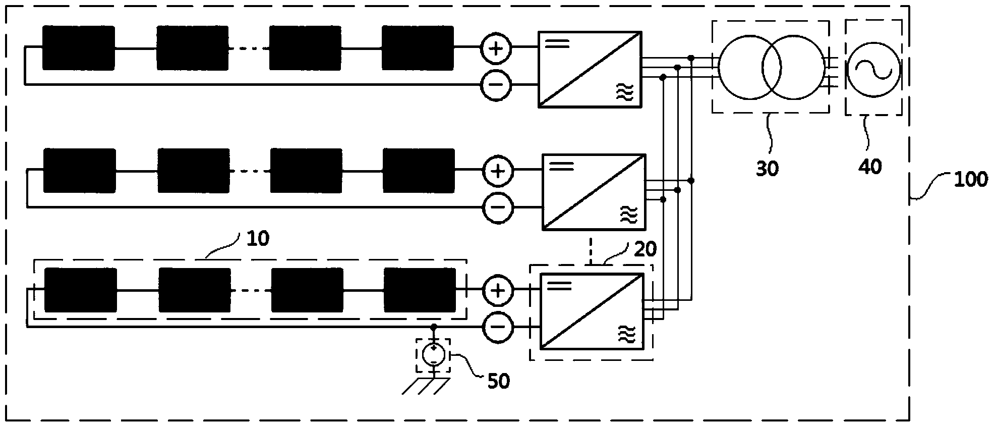
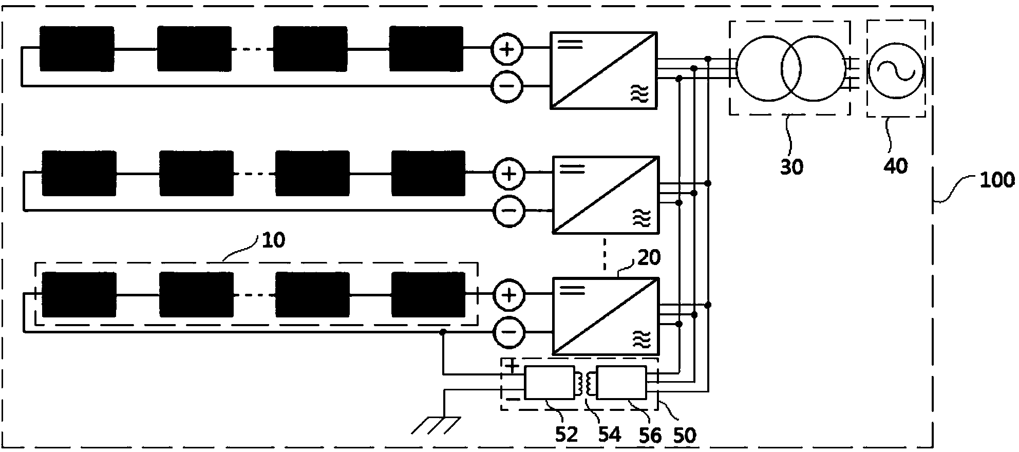
[0033] Please refer to figure 2 , the photovoltaic power supply system 100 provided by the present invention includes M photovoltaic cell assemblies 10 , N photovoltaic inverters 20 , an isolation transformer 30 and a grid 40 .

[0034] The photovoltaic inverter 20 includes a first input terminal and a first output terminal, any one of the first input terminals has at least one photovoltaic cell assembly 10 connected in, and the first output terminal is connected in parallel and electrically connected to all The isolation transformer 30, the isolation transformer 30 is electrically connected to the grid 40, wherein, N is an integer greater than or equal to 1, and M is an integer greater than or equal to 1.

[0035] The transformer 30 includes a second input terminal and a se...


PUM


Abstract

The invention discloses a photovoltaic power supply system. The photovoltaic power supply system comprises M photovoltaic cell components, N photovoltaic inverters, a voltage source and a power grid. Each photovoltaic inverter comprises a first input terminal and a first output terminal. At least one photovoltaic cell component is connected to any first input terminal. The first output terminals are in parallel and electric connection with the power grid. The first input terminals are grounded through the voltage source. The N is an integer larger than or equal to 1, and the M is an integer larger than or equal to 1. According to the photovoltaic power supply system, the voltage source is connected between the first input terminal of any photovoltaic inverter and the ground, so that the photovoltaic cell components of the whole photovoltaic power supply system are all under positive bias, generation of photovoltaic PID (potential induced degradation) effects is inhibited, degradation of the photovoltaic cell components is reduced, and power generation capacity of the photovoltaic power supply system is improved.

Description

technical field [0001] The invention relates to a photovoltaic power supply system. Background technique [0002] In 2005, the German SUNPOWER company found that the long-term high voltage of the photovoltaic module caused leakage current between the glass and the packaging material, and a large amount of charge accumulated on the surface of the battery, which deteriorated the passivation effect of the battery surface and caused the performance of the photovoltaic module to be lower than the standard design. As a result, the power generation efficiency is attenuated, which is the potential induced degradation (Potential Induced Degradation, PID) of photovoltaic modules; in 2010, NREL and Solon confirmed that regardless of the technology of P-type crystalline silicon cells used in photovoltaic modules, photovoltaic modules in There is a risk of PID under negative bias. The latest research results show that after a few years of negative bias of photovoltaic modules, the maxim...

Claims


Application Information

Patent Timeline
Patent Type & Authority Applications(China)
IPC IPC(8): H02S40/30H02S40/32
CPCY02E10/50
Inventor 彭书芳
Owner 彭书芳
Why Eureka
Try Eureka