
Method and Arrangement for the Detection of an Object in a Radar Field

Inactive Publication Date: 2014-06-05
JENOPTIK ROBOT GMBH
View PDF13 Cites 23 Cited by
  • Summary
  • Abstract
  • Description
  • Claims
  • Application Information

AI Technical Summary

Benefits of technology

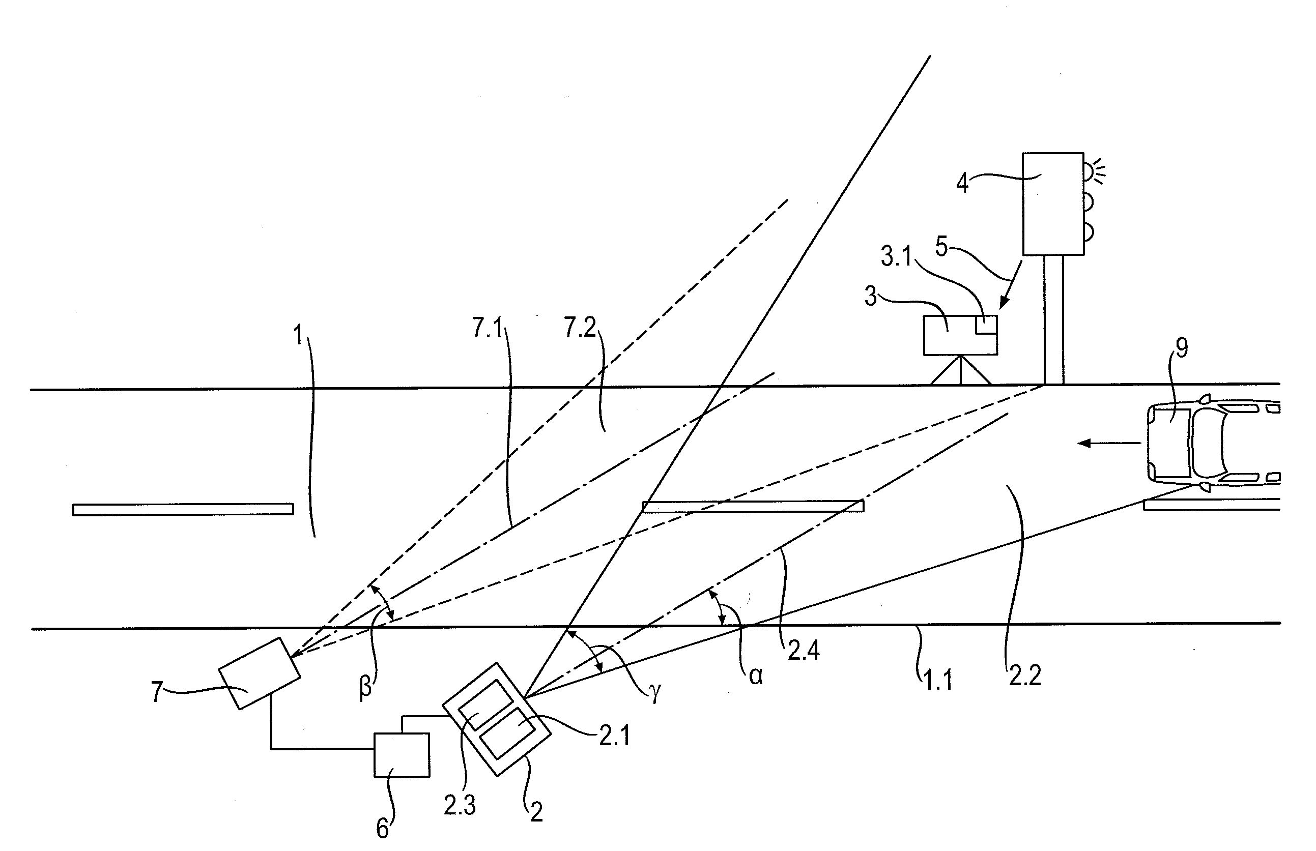
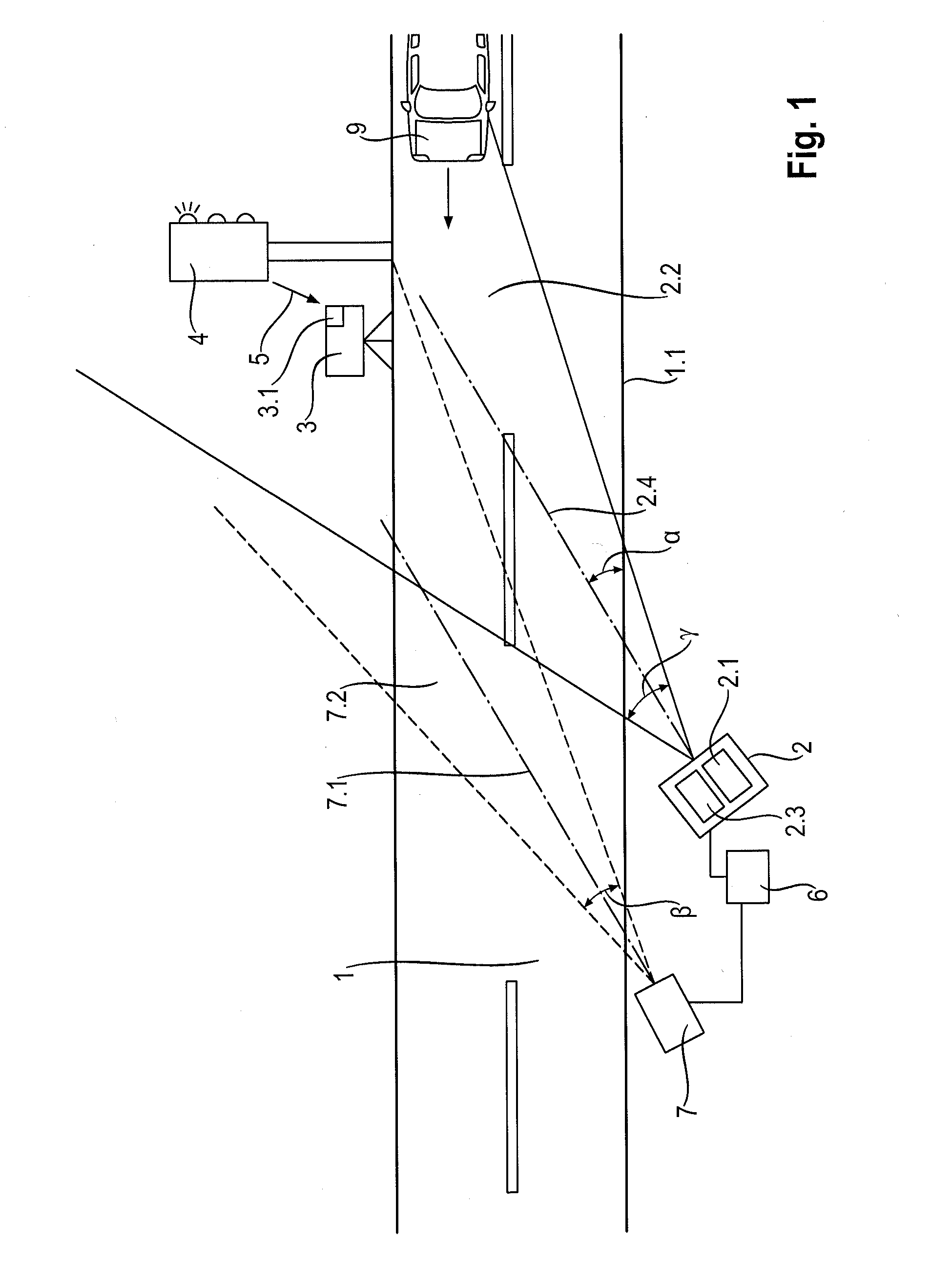
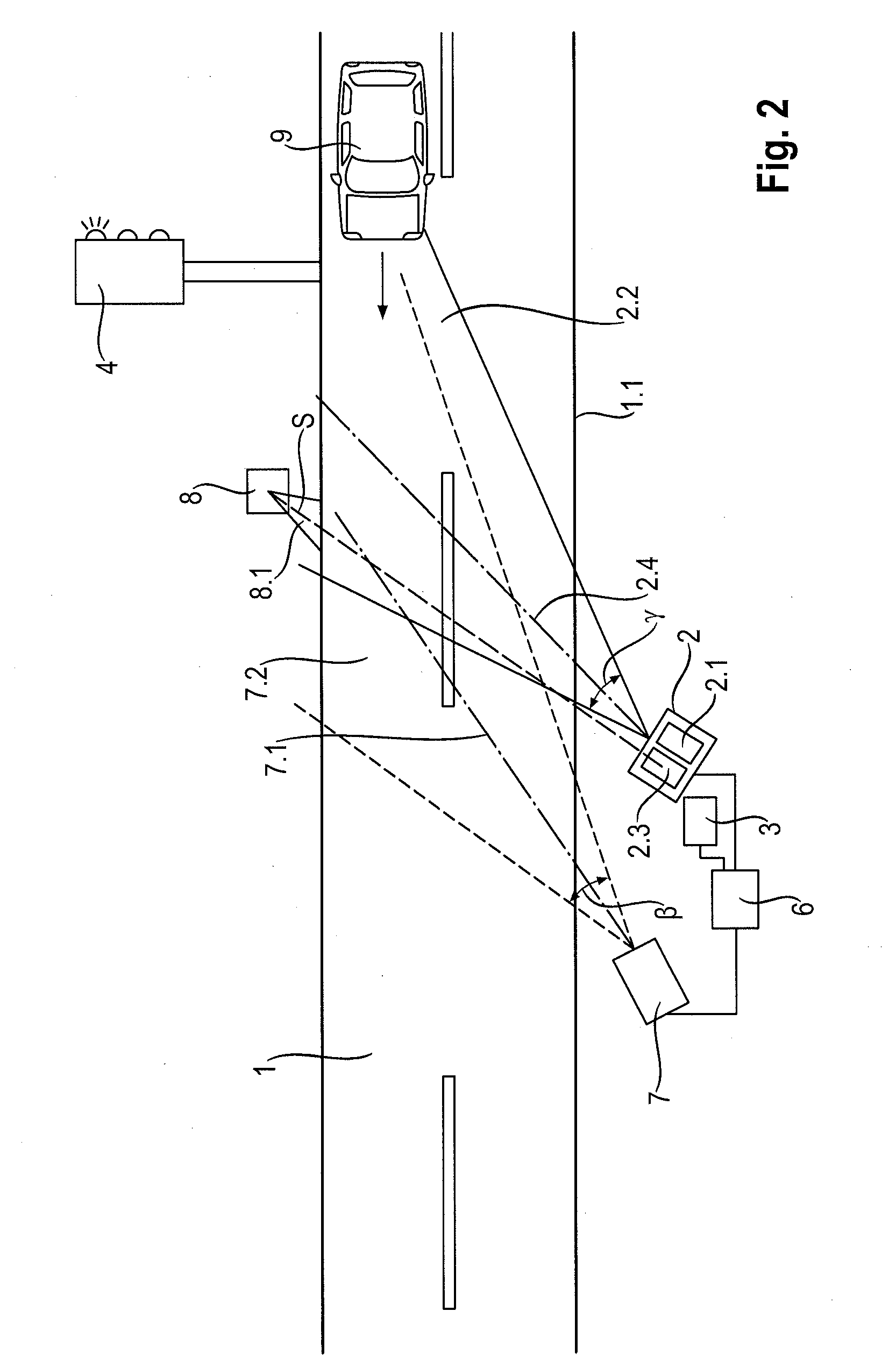
The patent describes a method to detect abnormal speed profiles using a radar device and a simulator. The simulator is controlled by a control device that can communicate wirelessly with the radar device. The method includes positioning reflectors in a way that creates a curtain of second radar fields in which movements can be detected. This allows for a larger horizontal area to be monitored. The use of the simulator as a light barrier also allows for detection of stationary vehicles without the need for expensive and over-sized sensors. The technical effect of this method is improved detection of abnormal speed profiles with reduced cost and complexity.

Problems solved by technology

This identification is limited to establishing that the given response signal originates from the transponder.
Therefore, use of the solution according to DE 30 00 876 A requires a quite significant expenditure on apparatus and computational overhead.
Wired data lines are disadvantageous particularly when longer distances must be covered or when roadways intervene between the signal device and the radar device.
The transmission quality of wireless data lines, particularly in radio transmission, may be substantially compromised in case of greater transmission distances by surrounding buildings, moving traffic, and other sources of interference.

Method used


Image

  • Method and Arrangement for the Detection of an Object in a Radar Field
  • Method and Arrangement for the Detection of an Object in a Radar Field
  • Method and Arrangement for the Detection of an Object in a Radar Field

Examples


Embodiment Construction

[0020]In a simple embodiment of the invention, the line of sight is an imaginary direct connection between simulator and radar device. In further embodiments, it can also be deflected by one or more reflectors so that the line of sight undergoes at least one change of direction between simulator and radar device.

[0021]In order to detect objects of different size classes, the course of the line of sight can be arranged in such a way that the height of the line of sight corresponds to a height of the objects to be detected (e.g., trucks or busses). For example, the simulator can be arranged at the edge of a roadway to be monitored and in an upper region of the radar field at a height above the greatest height of an average passenger car but below the greatest height of an average truck or bus. The line of sight extends in an ascending manner from the radar device to the simulator and is only interrupted when an object of corresponding height is located in the line of sight. In so doin...


PUM


Abstract

A method and arrangement for detecting an object in a radar field (2.2) in which a simulator (3) arranged in a stationary manner in a radar field (2.2) of a radar device (2), which is outfitted with a radar transmitter (2.1) and a radar receiver (2.3), is suitable for simulating a speed profile which is defined by temporally consecutive speed changes. The simulator (3) is actuated in such a way that it simulates at least one predetermined atypical speed profile which cannot be associated with any expectable moving object so that, in addition to reflection signals from objects moving through the radar field (2.2), the radar receiver (2.3) receives simulator signals caused by the simulator (3), and status information associated with the atypical speed profile derived from these simulator signals.

Description

RELATED APPLICATIONS[0001]The present application claims priority benefit of German Application No. DE 10 2011 056 432.2 filed on Dec. 14, 2011, the contents of which are incorporated by reference in their entirety.BACKGROUND OF THE INVENTION[0002]The invention is directed to a method for the detection of an object in a radar field and to an arrangement for implementing the method.[0003]It is known from the art to use radar radiation to detect speeds of moving objects. The possibility of measuring a distance and an angular position of an object relative to the radar device by means of radar radiation is likewise known.[0004]Particularly when using mobile radar devices and radar devices employed for the acquisition of and probative documentation of measurement data, it is necessary to routinely check these measurement data. It is known for purposes of checking and aligning the radar device to install a simulator in the radar field of the radar device to be tested and to simulate a kn...

Claims


Application Information

Patent Timeline
IPC IPC(8): G01S7/40
CPCG01S7/4052G01S13/92G01S7/006G01S7/4004G01S7/4026G01S7/4056G01S13/867G01S13/91G09B9/54G08G1/04G08G1/052G09B19/14G01S7/4091G01S7/4095
Inventor LEHNING, MICHAEL
Owner JENOPTIK ROBOT GMBH
Learn More