Valve assemblies for expandable implants and tissue expanders

a valve and implant technology, applied in the field of medical devices, can solve the problems of insufficient interior fluid pressure to prevent leakage, large valves used in these implants, and inability to adjust the implants, etc., and achieve the effect of small volumetric space and minimal likelihood of fluid leakag

Active Publication Date: 2014-06-05
MENTOR WORLDWIDE
View PDF2 Cites 11 Cited by
  • Summary
  • Abstract
  • Description
  • Claims
  • Application Information

AI Technical Summary

Benefits of technology

[0028]In one embodiment, in order to minimize the likelihood of fluid leakage as the filling tube is removed from the valve assembly, a small volumetric space, gap and / or groove is created in the middle of the insertion pathway for the filling tube. The gap divides the insertion pathway into a proximal section and a distal section. After filling the implant and while withdrawing the filling tube from the valve assembly, if the distal section of the insertion pathway is unable to seal itself before any back pressure from within the implant causes fluid to pass completely through the distal section, the fluid that escapes from the distal section will be diverted into the at least one gap formed in the self-sealing material. The time that elapses as the escaping fluid or solution fills the gap provides time for the proximal section of the insertion pathway to seal. In one embodiment, the volume and dimensions of the gap may be modified to compliment the specific properties of the self-sealing silicone material used. In one embodiment, providing at least one gap enables the overall length of an insertion pathway to be shorter than otherwise possible.

Problems solved by technology

The valves used in these implants tend to be large and palpable.
Permanent implants, e.g., breast implants, have filling tubes which may be used to add and withdraw fluid, however, these implants typically do not allow for adjustment of the implant after the filling tube is removed.
Unfortunately, in use, it has been observed that the interior fluid pressure is not sufficient to prevent the leakage of fluid through the valve.

Method used


Image

  • Valve assemblies for expandable implants and tissue expanders
  • Valve assemblies for expandable implants and tissue expanders
  • Valve assemblies for expandable implants and tissue expanders

Examples


Embodiment Construction

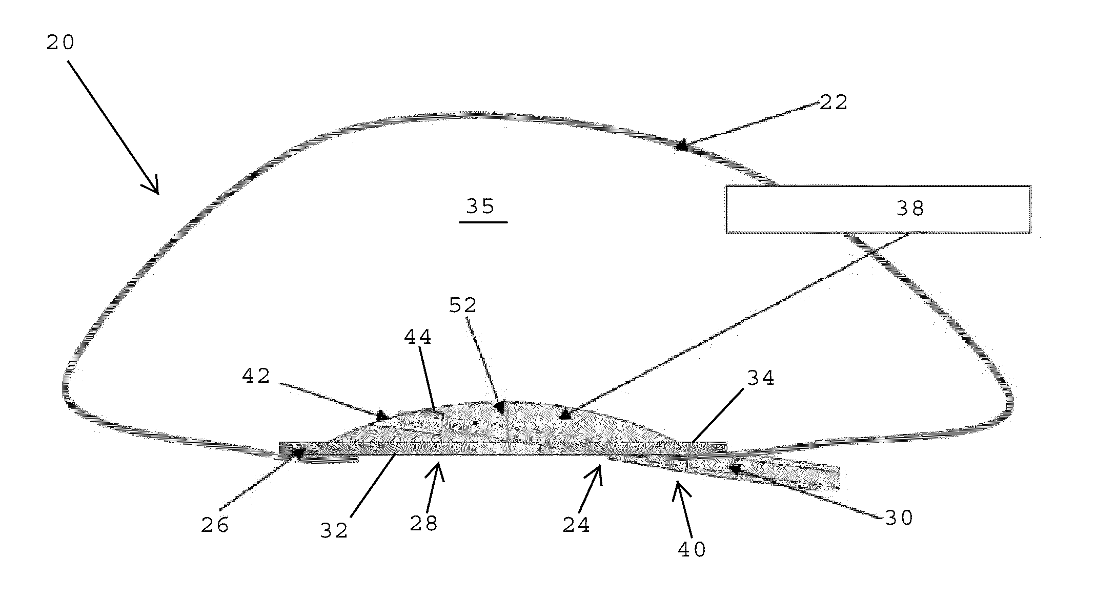
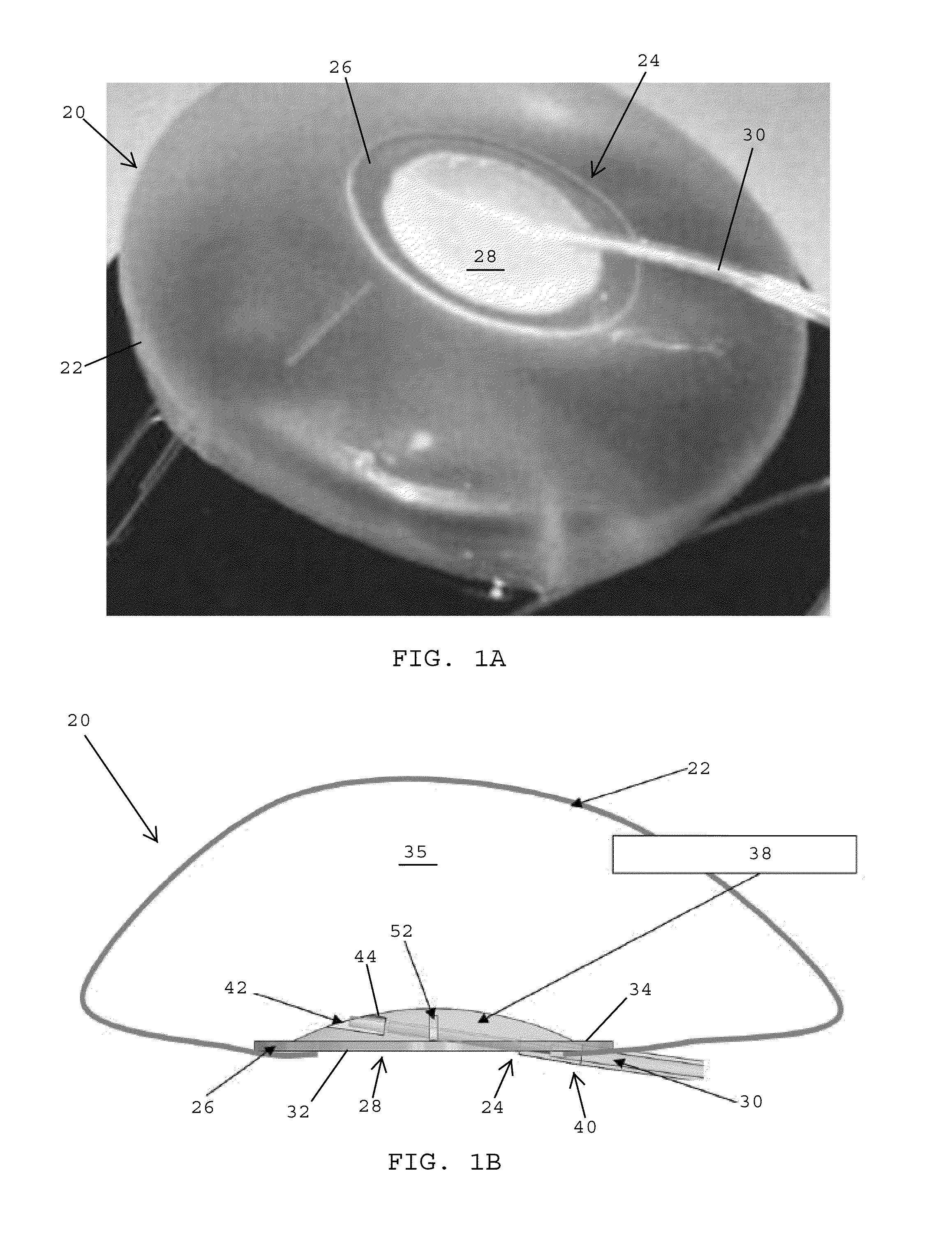
[0039]Referring to FIGS. 1A and 1B, in one embodiment, an expandable implant 20, such as a breast implant or tissue expander, preferably includes an outer shell 22 made of a flexible, biocompatible material such as silicone. The outer shell 22 is adapted to be filled with a solution, such as a saline solution, silicone gel, foam, or combinations thereof. The outer shell 22 desirably has an opening 24 that is closed by a biocompatible patch 26 of a valve assembly 28. In one embodiment, the valve assembly 28 is adapted to receive a filling tube 30 that enables the biocompatible solution to be added to or withdrawn from the outer shell 22 for adjusting the size of the expandable implant 20.

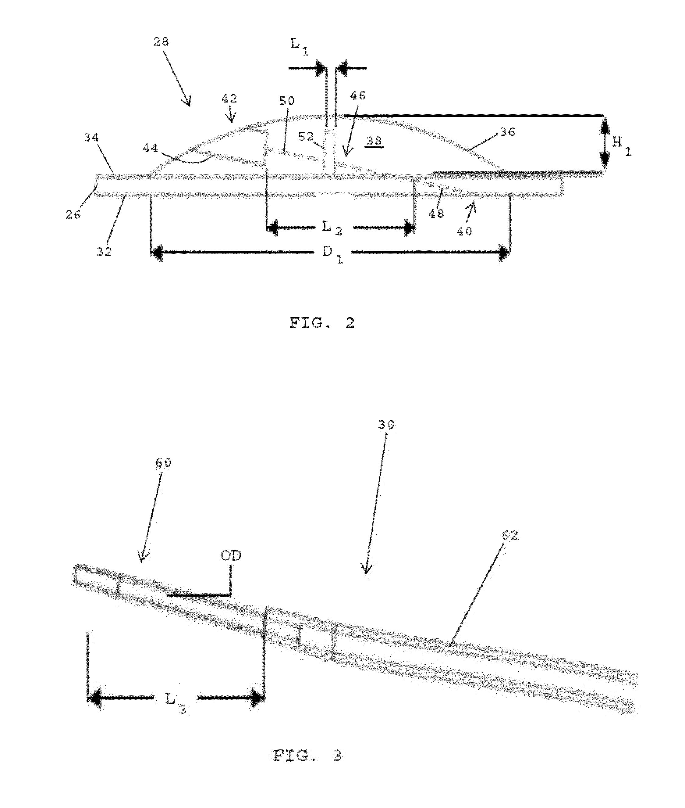
[0040]Referring to FIGS. 1B and 2, in one embodiment, the valve assembly 28 desirably includes the biocompatible patch 26 that is secured to the opening 24 of the outer shell 22 of the expandable implant 20 (FIG. 1B) to close and seal the opening in the outer shell. The patch 26 desirably includes an...


PUM


Abstract

A valve assembly for an implant has an inner shell, a self-sealing material disposed within the inner shell, and an insertion pathway extending through the self-sealing material. At least one gap is formed in the self-sealing material that intersects with the insertion pathway to define a proximal pathway section and a distal pathway section. A filling tube is passed through the valve assembly for filling the outer shell of the implant with a fluid. After the implant is filled, the filling tube is removed. As the filling tube is removed, if the self-sealing material within the distal section of the pathway is unable to self-seal before the fluid reaches its proximal end, the fluid is diverted into the gap. The time that elapses before the gap is completely filled by the fluid provides sufficient time for the self-sealing material within the proximal section of the pathway to self-seal.

Description

BACKGROUND OF THE INVENTION[0001]1. Field of the Invention[0002]The present invention generally relates to medical devices, and more specifically relates to valve assemblies for implantable prostheses and tissue expanders.[0003]2. Description of the Related Art[0004]Implantable prostheses are commonly used to replace or augment body tissue. In instances of breast cancer, it may be necessary to remove some or all of the mammary gland and surrounding tissue. This surgery leaves a void that can be filled with an implantable prosthesis that supports surrounding tissue and provides a normal body appearance, eliminating much of the shock and depression that often follows breast cancer surgeries. Implantable prostheses may also used for breast augmentation procedures.[0005]Tissue expanders are implantable devices that are placed beneath the skin and then gradually inflated to stretch the overlying tissue. Tissue expanders are commonly used to create a pocket for receiving a permanent prost...

Claims


Application Information

Patent Timeline
Patent Type & Authority Applications(United States)
IPC IPC(8): A61F2/12
CPCA61F2/12A61F2250/0003
Inventor DAVODIAN, AMIR
Owner MENTOR WORLDWIDE
Why Eureka
Try Eureka