Coolant jacket for a turbocharger oil drain

Active Publication Date: 2014-06-12
FORD GLOBAL TECH LLC
View PDF21 Cites 13 Cited by
  • Summary
  • Abstract
  • Description
  • Claims
  • Application Information

AI Technical Summary

Benefits of technology

[0002]Engines may use a turbocharger to increase engine torque/power output density. In one example, a turbocharger may include a compressor and a turbine connected by a drive shaft, where the turbine is coupl

Problems solved by technology

For example, heat flux near the turbocharger may affect the oil supply and/or oil drain of the turbocharger.
An increased heat flux can result in overheating and associated carbonization or coking of the lubricating oil, clogging the supply and/or drain, and thus reducing turbocharger lubrication.
As the turbocharger operates at high rotational speeds, reduced lubrication can result in bearing degradation, thus reducing engine performance.
Further, coking may occur at various locations, including

Method used


Image

  • Coolant jacket for a turbocharger oil drain
  • Coolant jacket for a turbocharger oil drain
  • Coolant jacket for a turbocharger oil drain

Examples


Embodiment Construction

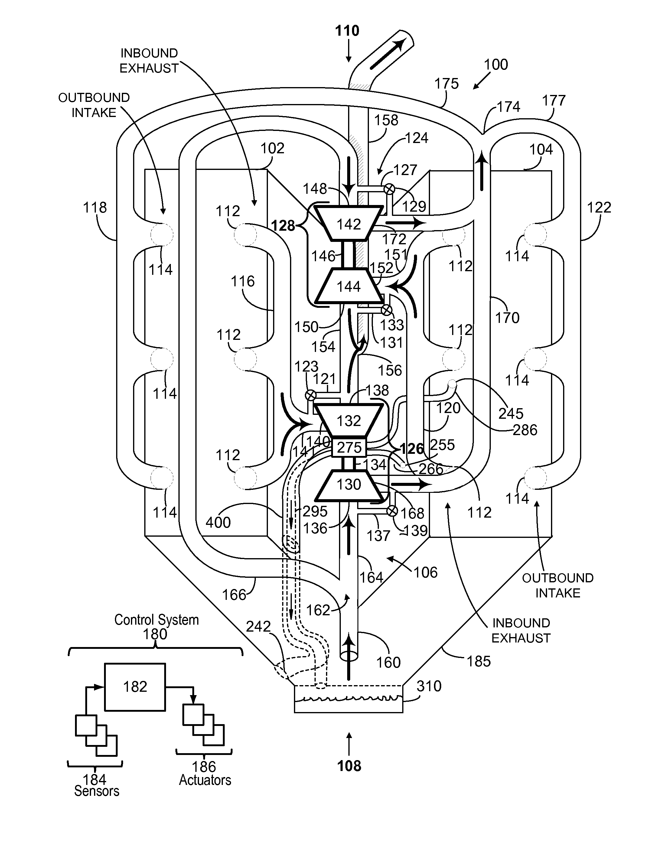
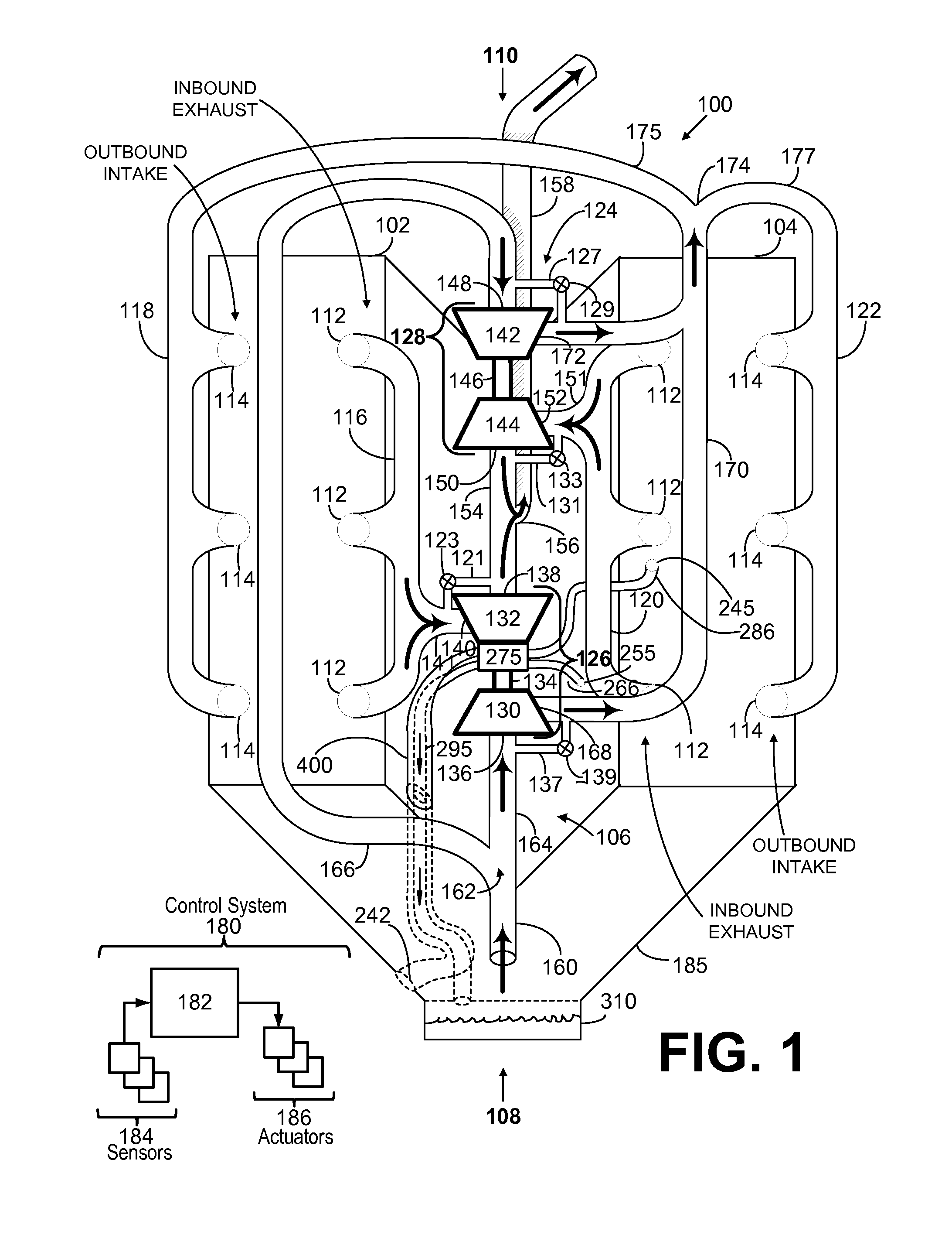
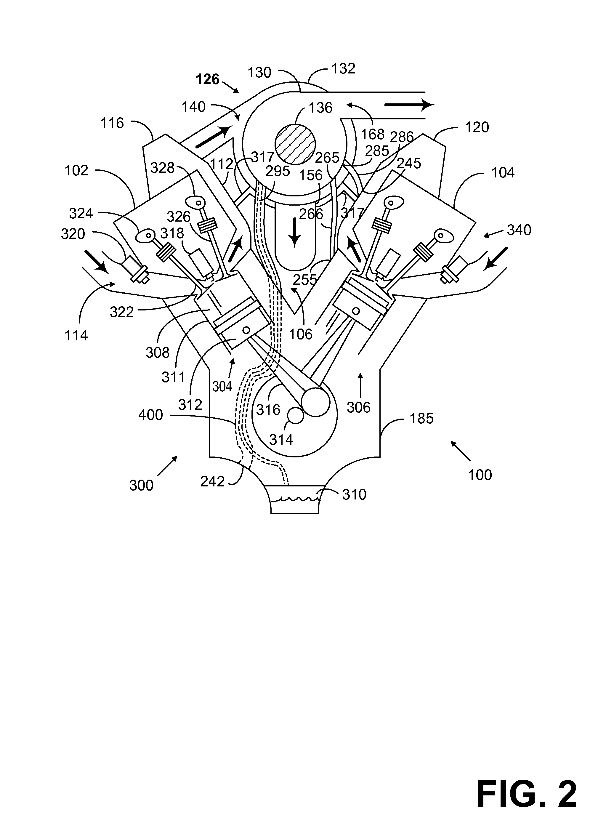
[0015]The present disclosure details a coolant jacket for an oil drain of a turbocharger. The coolant jacket is suitable to draw heat from oil as it leaves the turbocharger. The oil used in the turbocharger functions as lubrication and coolant for rapidly spinning components. Oil within the turbocharger is exposed to high heat because of the rapid spinning of the turbine, the drive shaft, and the compressor impellor and also the heat of exhaust gases used to propel the turbine. This high heat can result in coking of lubricating oil which leaves damaging residues on turbocharger components and decreases lubricating abilities within the turbocharger. Providing a coolant jacket for a turbocharger oil drain, in parts, or along its entirety may mitigate coking within the narrow oil drain. Coking within the oil drain may cause restrictions and further inhibition to turbocharger lubrication. This may be especially relevant in turbochargers mounted in the valley of V-type engines where the ...


PUM


Abstract

A system including a turbocharger, comprising a turbocharger bearing housing supporting a turbocharger drive shaft; an oil drain including an inlet in fluidic communication with the turbocharger bearing housing and an outlet in fluidic communication with an oil sump; and a coolant jacket enveloping the oil drain. The coolant jacket envelopes the oil drain and is positioned to provide coolant to the turbocharger bearing housing and draw heat from the oil draining through the oil drain to prevent coking of hot oil within the oil drain.

Description

TECHNICAL FIELD[0001]The present disclosure relates to turbochargers for internal combustion engines.BACKGROUND AND SUMMARY[0002]Engines may use a turbocharger to increase engine torque / power output density. In one example, a turbocharger may include a compressor and a turbine connected by a drive shaft, where the turbine is coupled to the exhaust manifold side and the compressor is coupled to the intake manifold side. In this way, the exhaust-driven turbine supplies energy to the compressor to increase the flow of air into the engine.[0003]In one example configuration, the drive shaft arranged between a compressor wheel and a turbine wheel is rotatably mounted in corresponding rotor bearings on the turbine side and the compressor side. The rotor bearings can generally be sliding bearings or roller bearings with oil lubrication, for example engine oil. The engine oil may be conducted to the individual bearing points via a pressure line, for example. The lubricant can both lubricate ...

Claims


Application Information

Patent Timeline
IPC IPC(8): F02B37/00
CPCF02B37/00F02B39/005F02B39/14F01D25/125F01P2060/12F05D2220/40
Inventor MATTHEWS, PATRICKWADE, ROBERT ANDREW
Owner FORD GLOBAL TECH LLC
Why Eureka
Try Eureka