Wastegate valve position correction

Active Publication Date: 2015-03-26
FORD GLOBAL TECH LLC
View PDF4 Cites 16 Cited by
  • Summary
  • Abstract
  • Description
  • Claims
  • Application Information

AI Technical Summary

Benefits of technology

[0002]Some internal combustion engines utilize a compression device such as a turbocharger to increase engine torque/power output density. In one example, a turbocharger may include a compressor and a turbine connected by a drive shaft, where the turbine is coupled to an exhaust manifold side and the compressor is coupled to an intake manifold side of an engine. In this way, the exhaust-driven turbine supplies energy to the compressor to increase the pressure (e.g. boost, or boost pressure) in the intake manifold and to increase the flow of air into the engine. The boost may be contr

Problems solved by technology

Depending on its location, the linkage may be subjected to significantly large forces, vibration, and temperat

Method used


Image

  • Wastegate valve position correction
  • Wastegate valve position correction
  • Wastegate valve position correction

Examples


Example

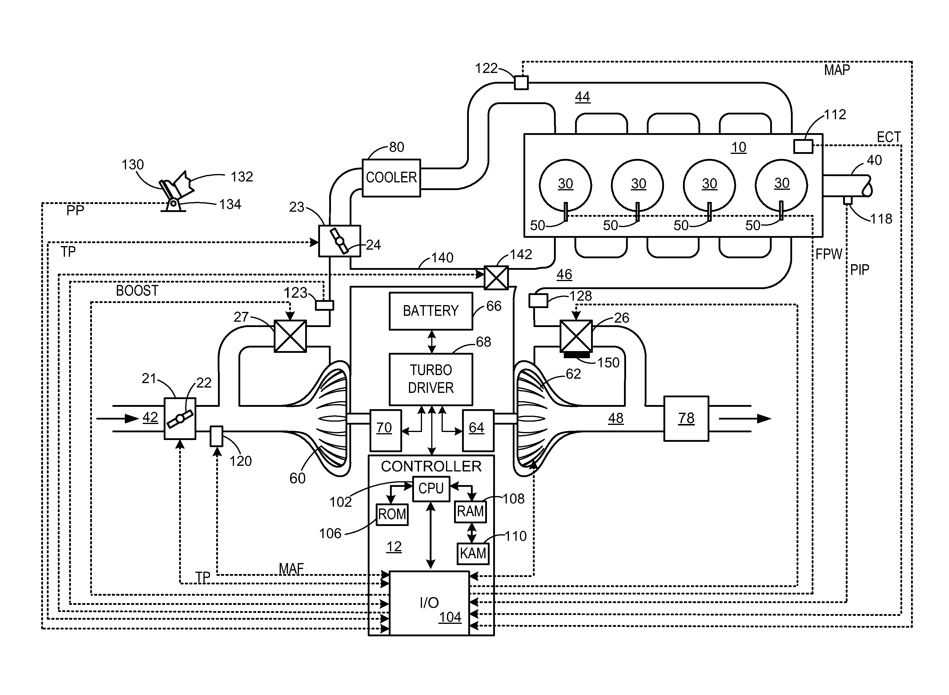
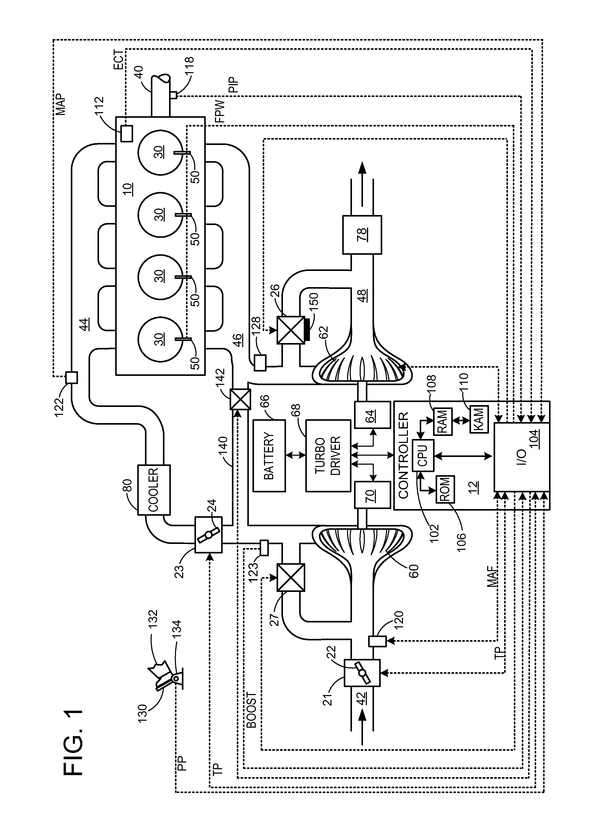
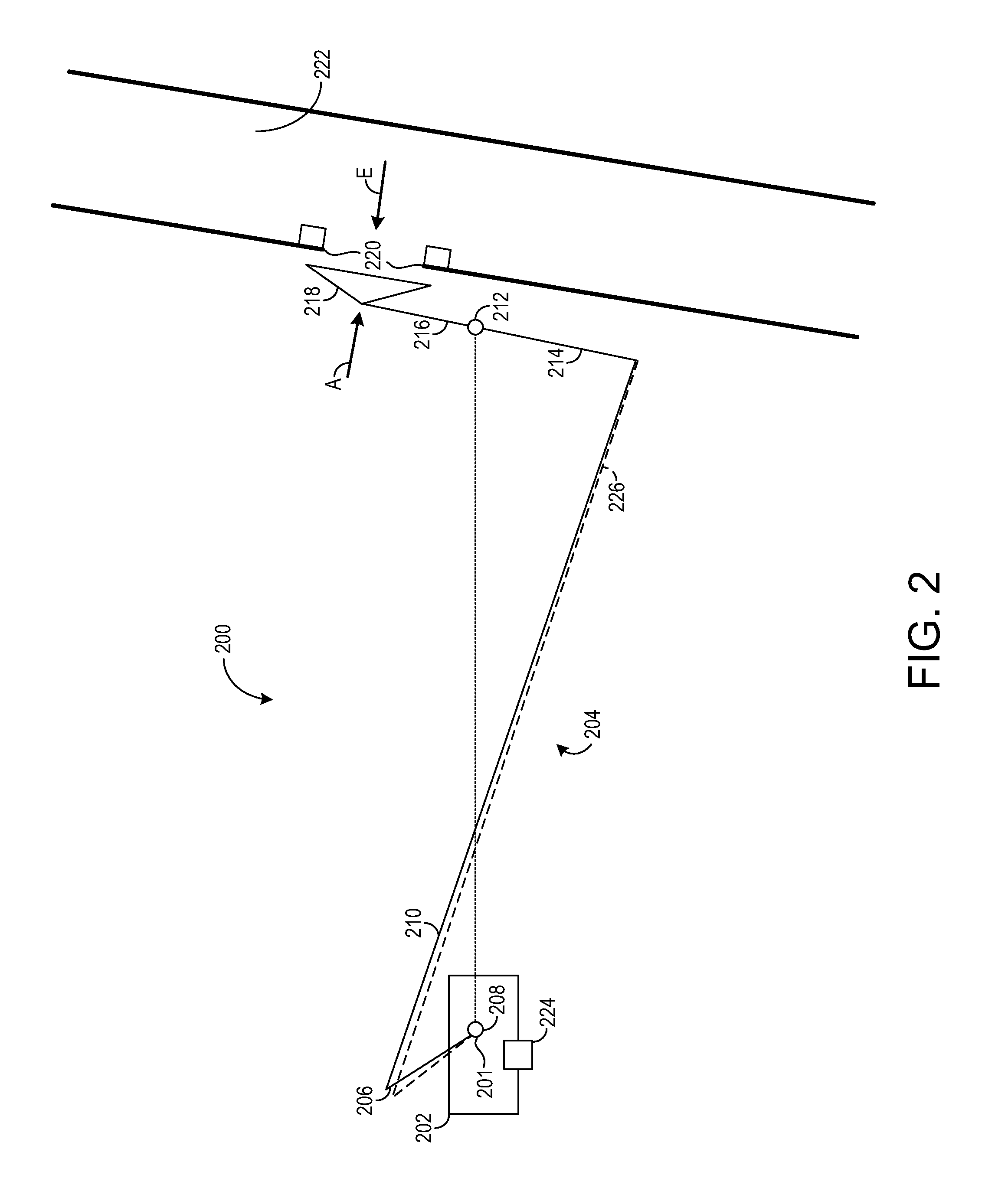
[0018]Compression devices such as a turbocharger may be used to increase the output of an internal combustion engine. A wastegate may in part regulate the boost pressure supplied to the engine by positioning a wastegate valve to thereby control the amount of exhaust gas reaching a turbine of the turbocharger. The wastegate valve may be positioned via an actuator with a linkage disposed therebetween. Deformation and / or deflection in the linkage, however, may prevent accurate wastegate valve positioning and thus accurate boost control. For example, actuator forces and exhaust forces acting on the linkage may cause the linkage to bend. In other scenarios, deflection may occur in the actuator itself and / or in a structure positioned between the wastegate valve and actuator mounting bosses. “Deflection” and “deformation” as used herein may refer to any or all of these scenarios. Compensating wastegate deflection in some examples may include compensating two or more constituent deflections...


PUM


Abstract

Various methods for compensating a deflected linkage in a wastegate arrangement are provided. In one example, current is applied to an actuator to move a wastegate valve coupled through a linkage to the actuator for diverting gasses from a turbocharger. The position of the actuator is indicated, and a correction to said indicated actuator position is applied compensating for deflection of the linkage based at least on said applied current. Said applied current is adjusted when said corrected actuator position reaches a position corresponding to a desired valve position.

Description

FIELD[0001]The disclosure relates to a control of a wastegate in a turbocharger.BACKGROUND AND SUMMARY[0002]Some internal combustion engines utilize a compression device such as a turbocharger to increase engine torque / power output density. In one example, a turbocharger may include a compressor and a turbine connected by a drive shaft, where the turbine is coupled to an exhaust manifold side and the compressor is coupled to an intake manifold side of an engine. In this way, the exhaust-driven turbine supplies energy to the compressor to increase the pressure (e.g. boost, or boost pressure) in the intake manifold and to increase the flow of air into the engine. The boost may be controlled by adjusting the amount of gas reaching the turbine, for example with a wastegate. An actuator may be operatively coupled via a linkage to a wastegate valve and driven to position the wastegate valve to achieve the desired boost based on operating conditions. The actuator may be an electric actuato...

Claims


Application Information

Patent Timeline
IPC IPC(8): F02B37/18
CPCF02B37/183F02B37/186F02B39/16Y02T10/12
Inventor WANG, YANMCCONVILLE, GREGORY PATRICKLAPHAM, KATHERINERUMPSA, TODD ANTHONYDERBAS, HAMZAKOKOTOVIC, VLADIMIR V.
Owner FORD GLOBAL TECH LLC
Why Eureka
Try Eureka