Particulate matter sensor

a technology of particle matter and sensor, which is applied in the direction of mechanical equipment, machines/engines, instruments, etc., can solve the problems of damage to the dpf by heat generated in the dpf regeneration process, and achieve the effect of ensuring a capacitance large enough for detection

Active Publication Date: 2014-06-12
ISUZU MOTORS LTD
View PDF1 Cites 10 Cited by
  • Summary
  • Abstract
  • Description
  • Claims
  • Application Information

AI Technical Summary

Benefits of technology

[0016]1) An average PM deposit quantity of the entire DPF can be detected.
[0017]2) A capacitance large enough for detection can be secured.

Problems solved by technology

At that time, when the PM deposit quantity is too large, the DPF is damaged by heat generated in the DPF regeneration.

Method used


Image

  • Particulate matter sensor
  • Particulate matter sensor
  • Particulate matter sensor

Examples


Embodiment Construction

[0027]Hereinafter, an embodiment of the present invention will be described with reference to the accompanying drawings.

[0028]First, the structure and function of a DPF will be described as the basis of the present invention.

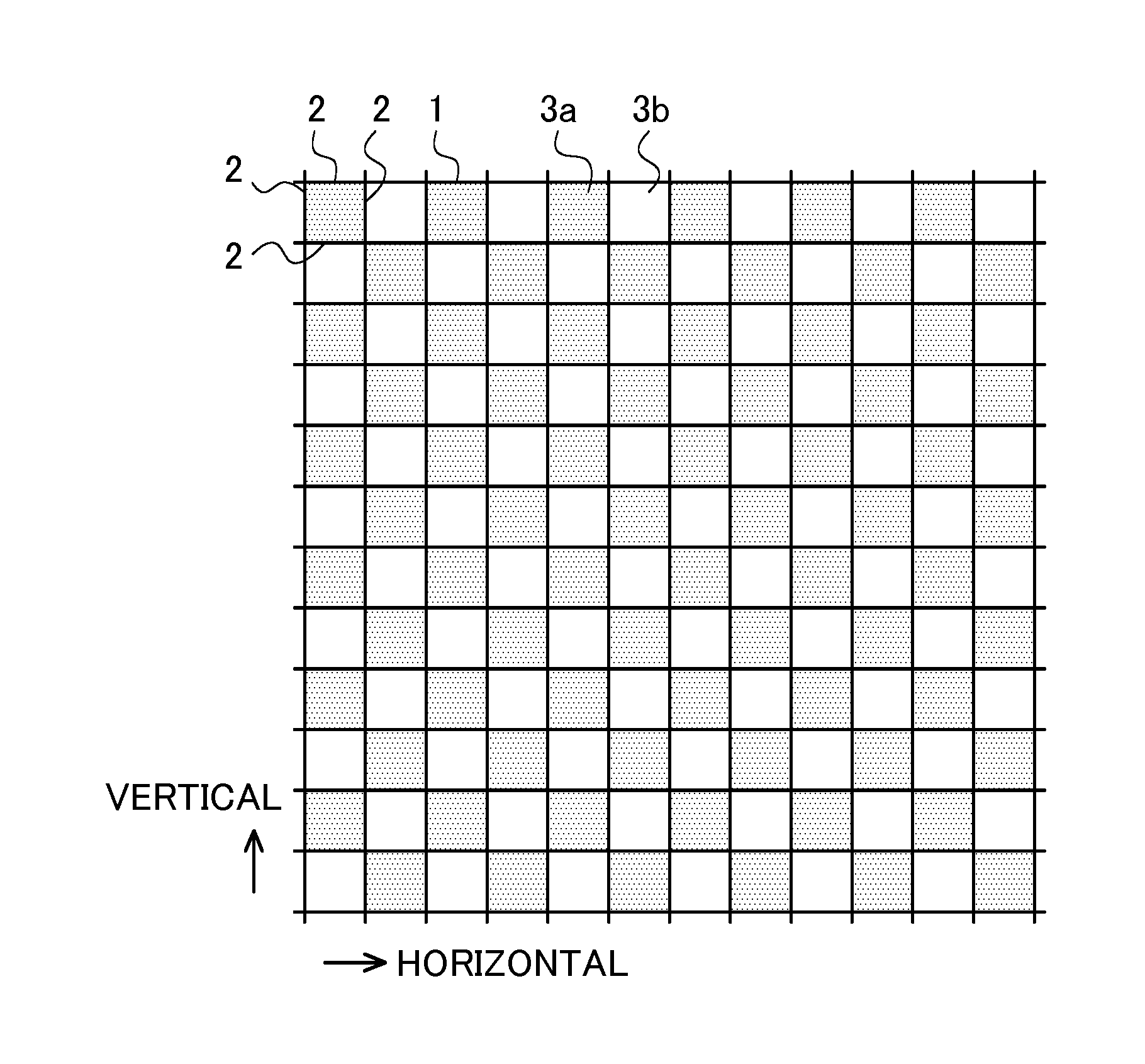
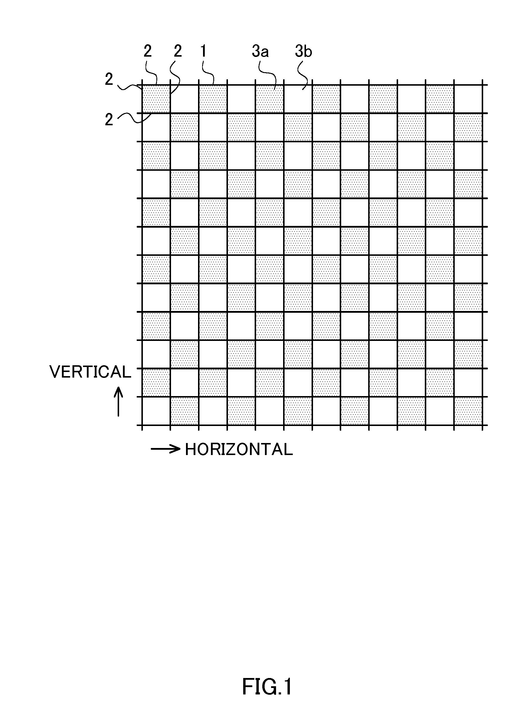
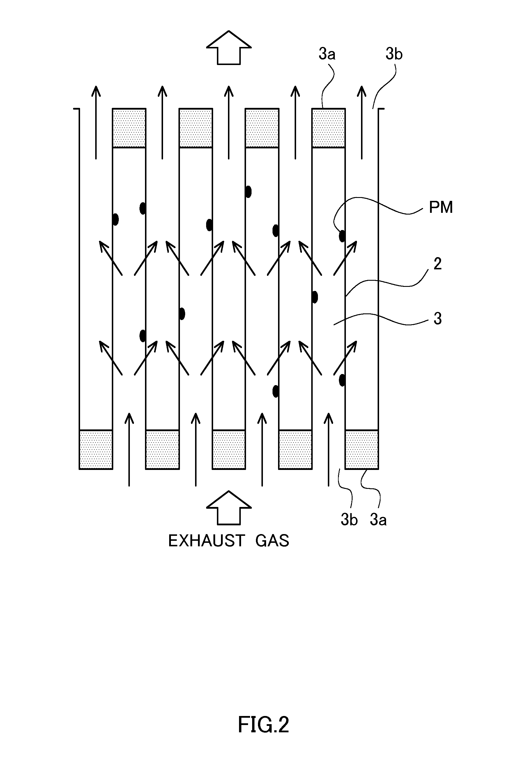
[0029]As illustrated in FIG. 1, the DPF 1 is obtained by vertically and horizontally stacking cells 3 in which all of vertical and horizontal sides are surrounded by walls 2 formed of a porous material and sealing end faces of the cells 3 alternately vertically and horizontally. In the drawing, the sealing is illustrated by hatching. Among the cells 3, the sealed cells are referred to as sealed cells 3a, and the cells which are not sealed are referred to as open cells 3b. As illustrated, the cells vertically adjacent to the sealed cell 3a and the cells horizontally adjacent to the sealed cells 3a are the open cells 3b, and the cells vertically adjacent to the open cell 3b and the cells horizontally adjacent to the open cell 3b are the sealed cells 3a. Although a...


PUM

PropertyMeasurementUnit
diameteraaaaaaaaaa
diameteraaaaaaaaaa
capacitanceaaaaaaaaaa

Abstract

A diesel particulate filter (“DPF”) including vertically and horizontally stacked cells in which all of vertical and horizontal sides are surrounded by walls formed of a porous material, and sealing end faces of the cells alternately vertically and horizontally are provided with first and second electrodes. In a particulate matter (“PM”) sensor in which a PM deposit quantity of the DPF is detected by a capacitance of a capacitor formed by the first and second electrodes, among open cells, the first electrodes are inserted into the open cells arranged in a line in a diagonal direction, and the second electrodes are inserted into the open cells arranged in a line in the diagonal direction and including the open cells secondarily adjacent to each of the open cells into which the first electrodes are inserted.

Description

TECHNICAL FIELD[0001]The present invention relates to a particulate matter (PM) sensor which can detect an average PM deposit quantity of the entire DPF and at the same time can ensure a capacitance large enough for detection.BACKGROUND ART[0002]In a vehicle equipped with an internal combustion engine, a diesel particulate filter (hereinafter referred to as DPF) is installed in an exhaust gas passage from the internal combustion engine to the atmosphere, and a particulate matter (hereinafter referred to as PM) is caught by the DPF. The DPF is a member which temporarily catches the PM on a filter formed of porous ceramics and having a shape of a honeycomb pore.[0003]If the amount of the PM caught by the DPF (hereinafter referred to as a PM deposit quantity) increases, the exhaust pressure of the internal combustion engine increases to lower the characteristics of the internal combustion engine, and therefore, processing for burning the caught PM is performed. This processing is refer...

Claims


Application Information

Patent Timeline
Patent Type & Authority Applications(United States)
IPC IPC(8): G01N27/22G01M15/10
CPCF01N3/0222F01N2560/05F01N2560/12G01N2015/0046G01N15/0656F01N13/008Y02T10/12G01M15/102G01N27/22
Inventor NODA, MASAFUMIUCHIYAMA, TADASHIASO, MITSUHIRO
Owner ISUZU MOTORS LTD
Why Eureka
Try Eureka