
Method of determining rotary angle related data of a vehicle wheel

a technology of rotary angle and related data, which is applied in the direction of measuring devices, instruments, using optical means, etc., to achieve the effect of improving accuracy and/or reliability of the apparatus and method

Active Publication Date: 2014-06-12
SNAP ON EQUIP
View PDF2 Cites 10 Cited by
  • Summary
  • Abstract
  • Description
  • Claims
  • Application Information

AI Technical Summary

Benefits of technology

The invention provides a method to determine the rotary angle of a rotating body, such as a vehicle wheel, by measuring the position of the body at different points in time. This is done without the need for a separate rotary angle sensor, reducing costs and the complexity of the apparatus. The method can also improve the accuracy and reliability of the measurement by using multiple sensors or a reference position signal. The measurement data can be used for various applications such as quality checking of wheels, rims, and assemblies, balancing of wheels, and improving the mounting position of wheels on rims.

Problems solved by technology

For example, scalar values of an imbalance of a wheel or a radial or lateral runout of a wheel or rim may be determined from measurement data having relative rotary angle information without information about the exact rotary position or direction of the non-uniformity if merely a quality evaluation is performed and it is not intended to correct the non-uniformity.

Method used


Image

  • Method of determining rotary angle related data of a vehicle wheel
  • Method of determining rotary angle related data of a vehicle wheel
  • Method of determining rotary angle related data of a vehicle wheel

Examples


Embodiment Construction

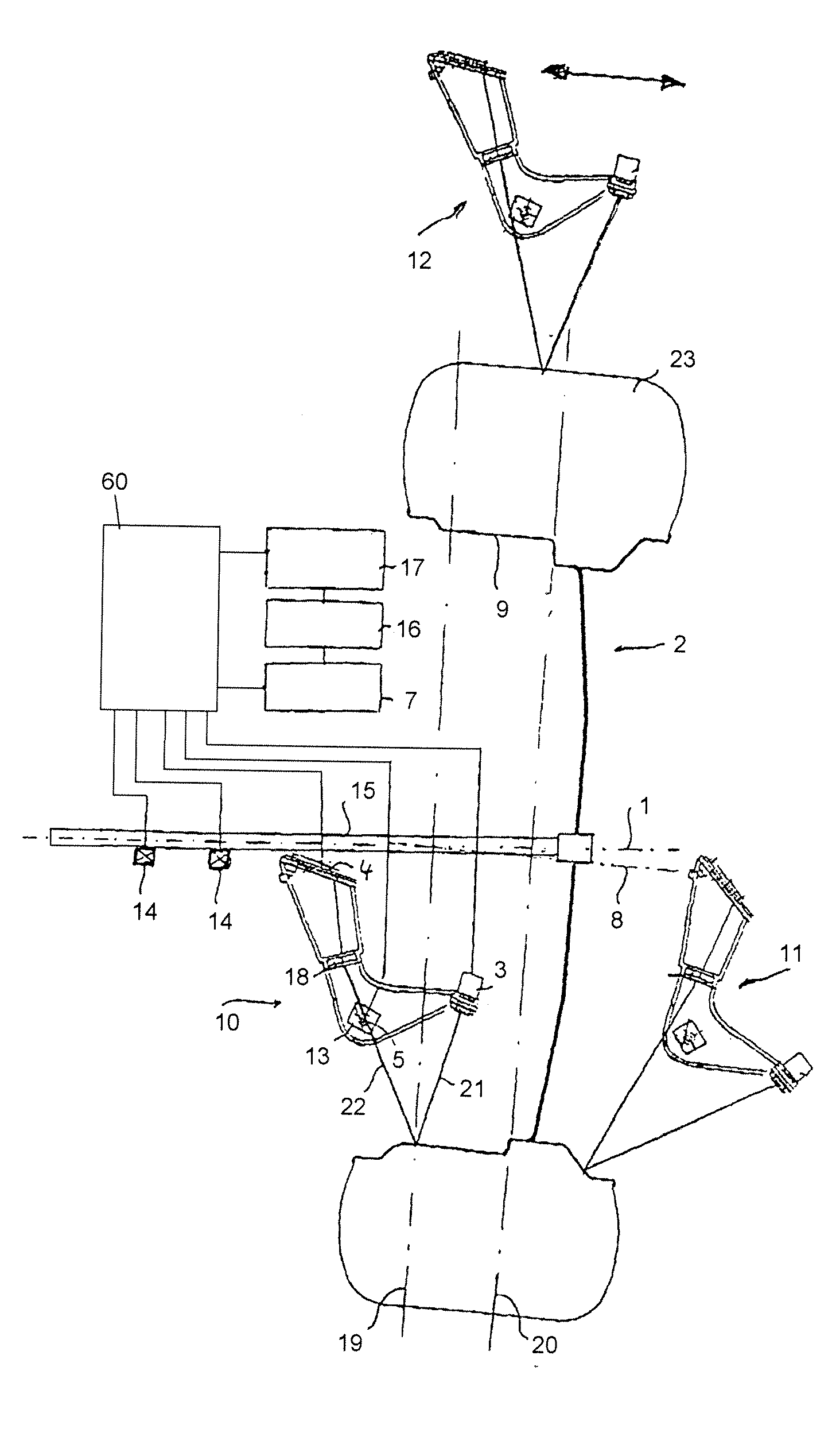
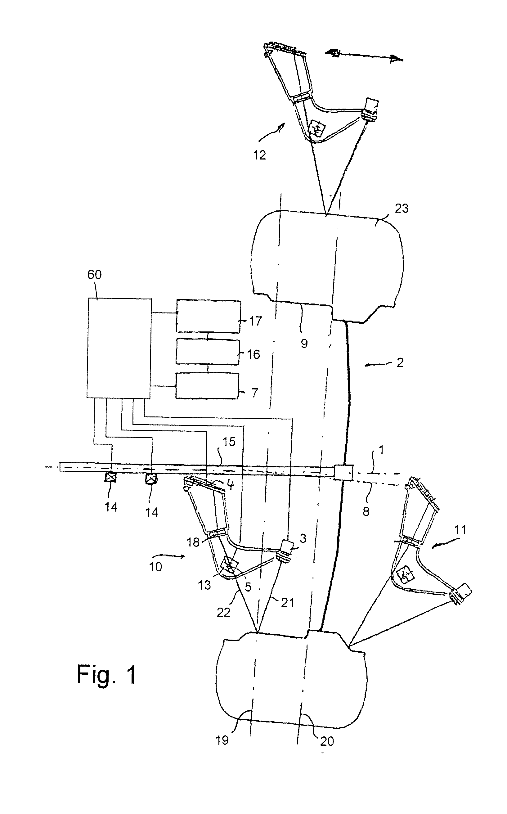
[0031]The illustrated preferred embodiment of the invention relates to a wheel balancer similar to that described in EP patent 1 398 610. This wheel balancer comprises three optical surface scanning devices (laser scanners) for contactless scanning the surface of a wheel and determines the geometrical shape of the tyre and the position of a geometrical axis of the wheel with respect to a rotational axis of the wheel (imperfect shape of the wheel rim and / or the tyre). It has to be noticed that the invention is not restricted to this special embodiment of a wheel balancer, but may be applied to a variety of vehicle wheel service apparatuses as described above.

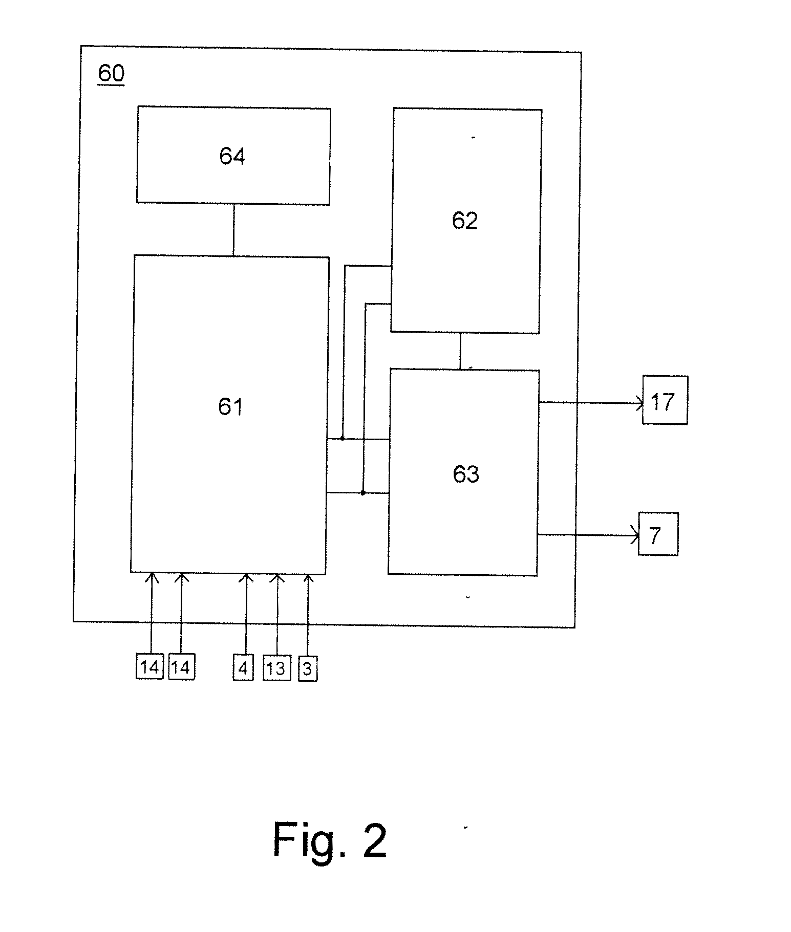
[0032]According to a first preferred embodiment of the invention shown in FIGS. 1 and 2, a wheel balancer comprises a main shaft 15 which is supported rotatable about an axis of rotation 1 on the frame structure of a wheel balancing machine (not shown) in known manner, for example as is illustrated in WO 00 / 14503. A motor vehicle...


PUM


Abstract

A method and an apparatus for determining rotary angle related measurement data of a body mounted rotatable about an axis of rotation, the body being a vehicle wheel or a part of a vehicle wheel, in particular a tyre or a rim, the method comprising the steps of obtaining measurement data comprising a plurality of measurement data elements of the rotating body together with respective measuring times, determining at least one rotational speed or revolution period of the body for at least one point in time, and associating the obtained measurement data elements to respective rotary angles of the body based on the respective measuring times and the at least one rotational speed or revolution period of the body.

Description

[0001]The invention concerns a method of determining rotary angle related data of a body, in particular a motor vehicle wheel or a part of a vehicle wheel mounted rotatable about an axis of rotation as set forth in the preamble of claim 1, and an apparatus for carrying out that method as set forth in the preamble of claim 12.BACKGROUND ART[0002]From EP patent application 1 731 891, a method and apparatus for obtaining rotary angle related data of vehicle wheels in a wheel balancer is known. In that wheel balancer, vibration forces caused by imbalance of the wheel and variations of forces caused by a load roller bearing against the tyre are determined with respect to the rotary angle of the wheel. The determined rotary angle related vibration force data is used to calculate sizes and mounting positions of balancing weights for balancing the wheel. The determined rotary angle related load force data is used to improve balancing operation.[0003]Another method or apparatus determining r...

Claims


Application Information

Patent Timeline
IPC IPC(8): G01M17/013
CPCG01M17/013G01B11/24G01B21/26G01B2210/26G01M1/225G01M17/04
Inventor BRAGHIROLI, FRANCESCO
Owner SNAP ON EQUIP
Learn More