
Directional Drilling Tool

a drilling tool and directional technology, applied in the field of oil and gas exploration, can solve the problems of affecting the drilling operation, and involving a significant amount of non-drilling time (ndt) in any drilling operation, and achieve the effect of a wide range of angle adjustmen

Inactive Publication Date: 2014-06-12
ZAKI MAGDY +2
View PDF14 Cites 10 Cited by
  • Summary
  • Abstract
  • Description
  • Claims
  • Application Information

AI Technical Summary

Benefits of technology

The patent describes a solution to problems in drilling operations by offsetting the upper section of the housing from the motor and allowing for remotely adjustable angles downhole. However, this still requires the drilling to be halted and the drill string lifted off-bottom, leading to non-drilling time. The technical effect is to provide a greater range of angle adjustment for the housing while minimizing non-drilling time.

Problems solved by technology

Firstly, the maximum bend angle between the longitudinal axes of the upper and lower sections of the housing is 2α, but the maximum angle is limited to a smaller angle downhole due to space constraints within the borehole.
Secondly, any adjustment of the housing must be carried out manually at the surface, adding to the time and associated costs of the drilling operation.
However, the drilling operation has to be halted and the drill string lifted off-bottom in order for the angular displacement of the upper and / or lower sections to be adjusted, thereby still involving a significant amount of non-drilling time (NDT) in any drilling operation.

Method used


Image

  • Directional Drilling Tool
  • Directional Drilling Tool
  • Directional Drilling Tool

Examples


Embodiment Construction

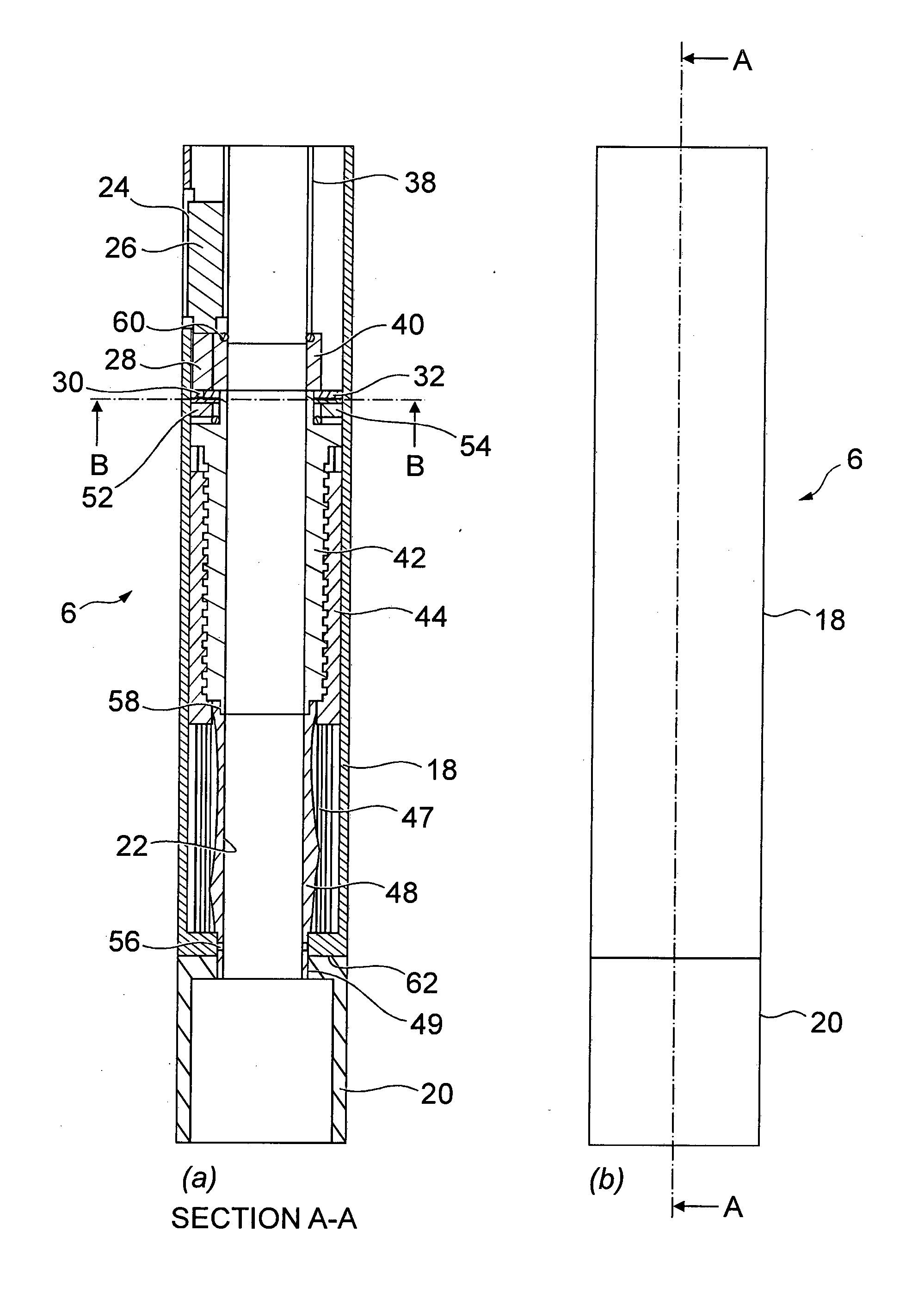
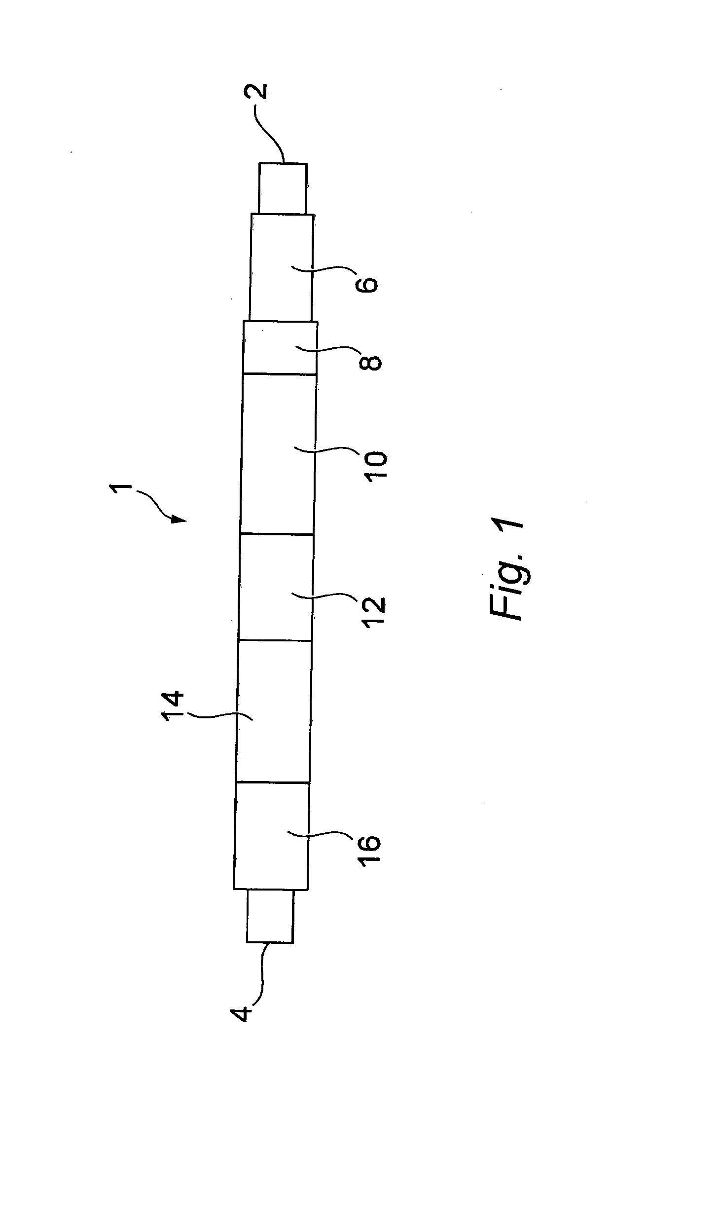
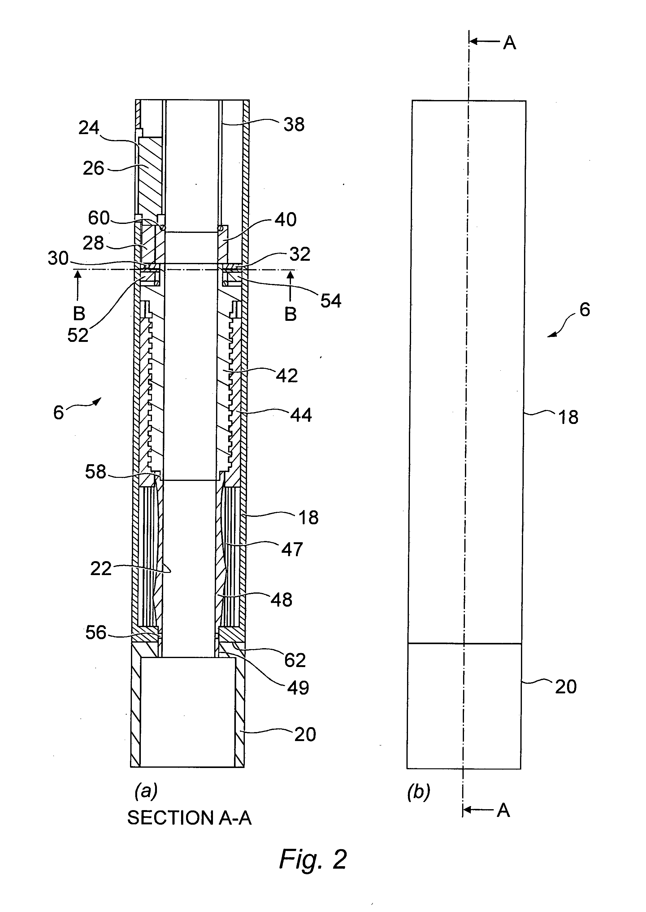
[0058]FIG. 1 schematically shows a directional drilling tool according to the present invention. The drilling tool, generally designated 1, comprises a first or upper end 2 connectable to a drill string (not shown) and a second or lower end 4 connectable to a drill bit (not shown in FIG. 1). The tool 1 further comprises a motorised swivel 6 having a first swivel member non-rotatably attached to the first end 2 and a second swivel member attached to the remainder of the tool 1. As will be explained in more detail below, the first and second swivel members may be selectively rotated relative to one another so as to rotate the tool 1 relative to the drill string.

[0059]Below the swivel 6, the tool 1 further comprises a dump valve section 8 and a power section 10, both of which are of a type known in the art. Below the power section 10 is an adjustable bend section, also known as a bent sub, 12 having a first bend member attached to the power section 10 and a second bend member attached ...


PUM


Abstract

A directional drilling tool is provided, which comprises a first end (2) attachable to a drill string, and a second end (4) attachable to a drill bit. A swivel section (6) is provided intermediate the first and second ends (2,4) and has a first swivel member (18) non-rotatably attached to the first end (2) and a second swivel member (20) rotatably coupled to the first swivel member (18) and rotatable relative thereto about a first axis of rotation which is co-axial with a longitudinal axis (LI) of the tool. A first actuator is adapted to selectively rotate the second swivel member (20) about the first axis of rotation. An adjustable bend section (12) has a first bend member (118) non-rotatably attached to the second swivel member (20) and a second bend member (120) rotatably coupled to the first bend member (118), where the first bend member (118) is co-axial with the longitudinal axis (LI), and the second bend member (120) is rotatable relative to the first bend member (118) about a second axis of rotation (R) which is at a non-zero angle relative to the longitudinal axis (LI). A second actuator is adapted to selectively rotate the second bend member (120) about the second axis of rotation (R). A directional drilling system incorporating the tool, a control process for the tool, and a motor drive for rotating a second body relative to a first body are also provided.

Description

TECHNICAL FIELD[0001]The present invention relates to the field of oil and gas exploration, and in particular downhole drilling activities. More specifically, the present invention is a remotely controlled directional drilling tool for use in downhole drilling.BACKGROUND ART[0002]It is known to utilise a Surface-Adjustable Bent (SAB) housing when drilling a well which has to follow a particular geometric path rather than one which is a “straight-hole”. The SAB housing typically forms part of a downhole drilling motor and is located between the power and bearing sections of the motor. The SAB housing comprises a fixed upper section connected to the power section of the motor, and a lower section which is rotatable relative to the upper section and connected to the bearing section and drill bit. The joint between the upper and lower sections of the SAB housing is angled such that the rotational axis of the lower section is at an angle α relative to the longitudinal axis of the upper s...

Claims


Application Information

Patent Timeline
IPC IPC(8): E21B7/06E21B44/00
CPCE21B44/00E21B7/067E21B7/06E21B17/05Y10T74/1836
Inventor ZAKI, MAGDYIBRAHIM, WALEEDAGUIB, KARIM
Owner ZAKI MAGDY
Learn More