Metering valve

a technology of metering valve and valve body, which is applied in the direction of mechanical equipment, transportation and packaging, and other domestic objects, can solve the problems of labor, cost, and difficulty in manufacturing mechanisms, and achieve the effect of high flow ra

Active Publication Date: 2014-06-12
SUMMIT PACKAGING SYST INC
View PDF4 Cites 18 Cited by
  • Summary
  • Abstract
  • Description
  • Claims
  • Application Information

AI Technical Summary

Benefits of technology

[0013]The addition of a lower sealing gasket or ring allows one or more larger diameter bore(s) to be radially formed in the lower portion of the valve stem without compromising the integrity of the valve stem itself. The bore shape and larger size can be selected to facilitate a high volume flow rate for highly viscous substances. For example a triangular or polygonal shape could provide a variable flow rate into and through the valve stem to ensure that highly viscous materials are dispensed at a desired flow rate depending on a user's actuation pressure. It is, therefore, an object of the present invention to overcome the above noted issues and produce a valve for both conventional aerosol valve and bag-on-valve systems which facilitates a high volume flow rate for liquids and semi-liquids of different viscosities.
[0015]The valve stem is initially filled with product through a priming actuation by fully or partially compressing the valve stem. Once primed, by compressing the valve stem, the propellant which may be a compressed gas forces the ball as a metering device off of a lower sealing rim to travel up and through the valve stem thereby dispensing the quantity of product within the valve stem. The ball engages an upper sealing rim at the outlet orifice of the valve stem to seal and prevent further product from being dispensed to the inlet passage of the actuator and nozzle. As the actuator is released, delivery of the product through the nozzle stops and the ball returns downward to a rest position on the lower sealing rim. The valve stem as the metering chamber is therefore filled with the pre-determined quantity of product for dispensing another metered dose. A small conduit may be provided at the upper sealing rim. The conduit provides communication between the valve stem and air external to the aerosol container in order to provide a pressure differential on each side of ball to release the ball from the upper sealing position after the valve is released. It is therefore an object of the invention to provide for a metering device within the valve stem to simplify the assembly and cost of a metering valve.
[0019]It is another object of the present invention to easily facilitate varying flow rates based on the point of depression of the valve.
[0020]It is a still further object of the present invention to provide a high volume flow rate for highly viscous substances that typically have difficulty being dispensed.
[0021]It is yet another object of the present invention to simplify the process of adding and discharging the contents of the aerosol can, container or product bag by allowing the product to go directly from the valve stem into the container or product bag without having to pass through the valve housing.
[0022]Another object of the present invention is to provide a two-way valve which permits a substantial increase in the speed of filling a product container or bag, especially in the context of highly viscous substances.

Problems solved by technology

The use of a metering device within a metering chamber is well known, with many aerosol valve designs of the prior art showing elaborate, costly and difficult to manufacture mechanisms having one or more mechanical springs, plungers, and other contrivances within the metering chamber to control the movement and positioning of the metering device.
By acting directly on the metering device, a common problem of using compressed or immiscible gas is alleviated, where the compressed gas is not valved off in a metering chamber and therefore left without means to dispel it therefrom.

Method used


Image

  • Metering valve
  • Metering valve
  • Metering valve

Examples


first embodiment

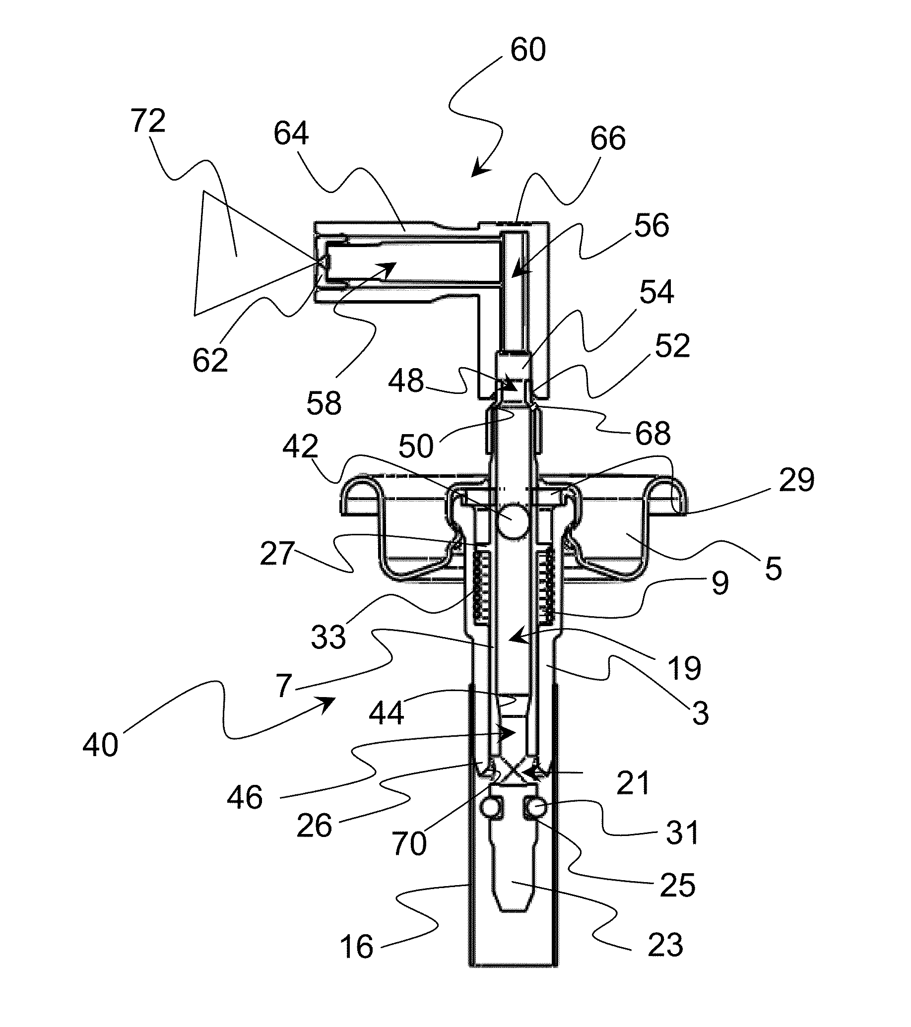
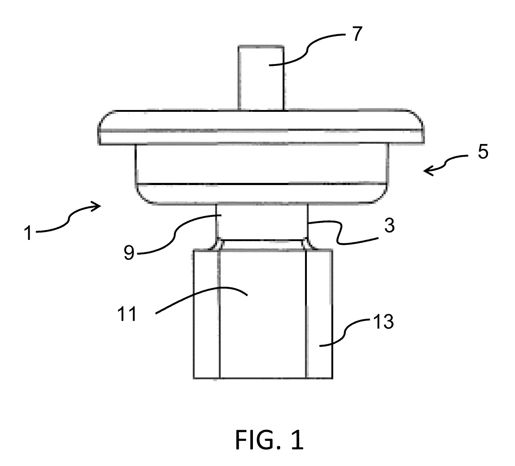
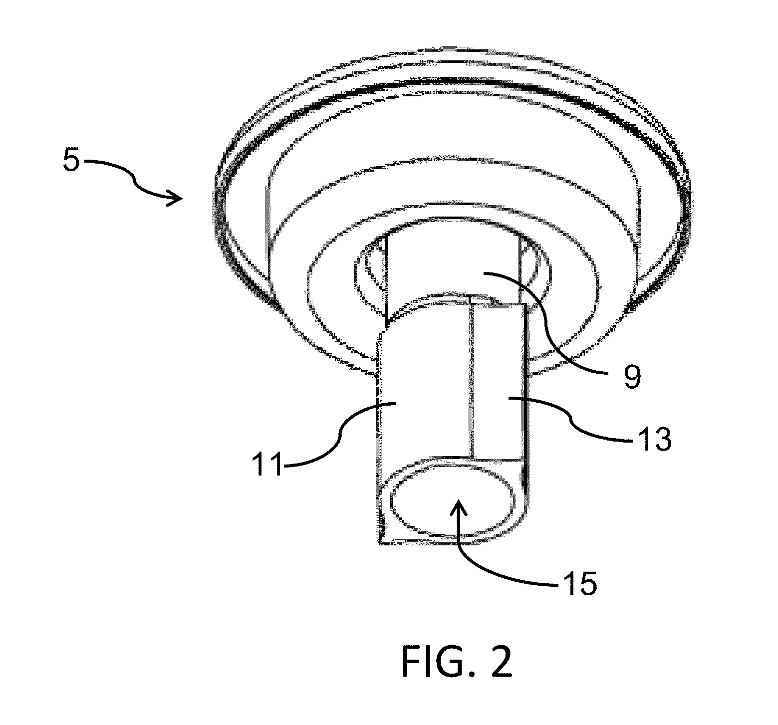
[0048]FIG. 1 illustrates a side view of an embodiment of the present invention illustrating the valve 1 in conjunction with the mounting cup 5 for a product containing can or container (not shown) in a bag-on-valve system. The valve stem 7 is parallel with and extends out of the valve housing 3 through the mounting cup 5. The valve housing 3 has multiple sections or portions that correspond to different functions for the bag-on-valve application. As is known in the art, a top portion of the valve housing is engaged generally by crimping with the mounting cup to secure the valve housing 3 to the mounting cup 5. The middle portion of the valve housing 3 is the spring cavity 9, which generally houses a spring for controlling dynamic movement between the valve stem 7 and the valve housing 3. The bottom portion 11 of the valve housing 3 can engage with either a dip tube, or as described in the first embodiment, with a product bag in the case of a bag-on-valve. In the present embodiment t...

second embodiment

[0058]Another important aspect of the present invention is the shape of the bores 35 which can facilitate control over dispensing of product at a high flow rate through the valve. FIG. 6 illustrates a side view of the valve stem 7 of the second embodiment with the bore 35 having a substantially circular shape. The bore 35 is a radial orifice in the sidewall of the valve stem 7, and adjacent the lower end thereof, which can be of a larger diameter than the 1.02 mm-1.52 mm (0.04-0.06 in.) diameter opening conventionally known, for example a diameter of between about 1.02 mm-3.81 mm (0.04-0.15 in) and more preferably in the range of about 2.03 mm-3.05 mm (0.08-0.12 in.) The larger bores 35 do not significantly affect the structural integrity of the valve stem 7 since the bores 35 are close to the bottom end of the valve stem where radial forces from depression and actuation of the valve stem 7 by a user are insignificant. Axial forces can significantly damage the valve stem where the r...


PUM

PropertyMeasurementUnit
diameteraaaaaaaaaa
cross-sectional areaaaaaaaaaaa
areaaaaaaaaaaa

Abstract

The present invention is directed to a metering valve used in both conventional and bag-on-valve aerosol container applications that allows a high flow rate of especially viscous substances. The metering valve according to the present invention including a valve housing, a valve stem, and a spring or other biasing device that allows the valve stem to move relative to the valve housing. The valve stem serves as a metering chamber with a metering device in the form of a ball or disk without other mechanisms such as springs or mechanical parts within the valve stem. Radial bores and a seal near the bottom of the valve stem provide for dispensing of pre-determined quantities of product from an aerosol container pressurized with liquefied propellants or compressed gas. The bore shape and size can be selected to facilitate a high volume flow rate for highly viscous substances.

Description

RELATED APPLICATION[0001]This application is a continuation-in-part application of and claims the benefit of pending U.S. application Ser. No. 12 / 859,078 filed Aug. 18, 2010 and published as U.S. Publication No. 2012 / 0043353 published on Feb. 23, 2012 and entitled HIGH FLOW AEROSOL VALVE which is hereby incorporated herein by reference in the entirety.FIELD OF THE INVENTION[0002]The present invention relates to a metering valve that dispenses a pre-determined quantity of material from a container under pressure of an aerosol or compressed gas that is simple in structure and readily manufactured. The present invention further relates to a high flow valve used in compressed gas, aerosol and bag-on-valve applications, and particularly to a valve having a housing that is supported by a mounting cup for a product container or can, and communicates with a product or product containment bag inside the can, where the radial opening of the valve is positioned closer to a lower seal of the va...

Claims


Application Information

Patent Timeline
Patent Type & Authority Applications(United States)
IPC IPC(8): B65D83/00
CPCB65D83/62B05B1/3066B65D83/48B65D83/54B65D83/546Y10T29/49412
Inventor DAVIDEIT, DANIEL E.VERVILLE, KEVIN G.
Owner SUMMIT PACKAGING SYST INC
Why Eureka
Try Eureka