Wireless power transmission system capable of continuing power transmission while suppressing heatup of foreign objects

a technology of power transmission system and foreign object, which is applied in the direction of charging stations, transportation and packaging, cycles, etc., can solve the problems of wireless power transmission system not being able to resume power transmission, foreign object heatup, etc., and achieve the effect of suppressing foreign object heatup

Active Publication Date: 2014-06-12
PANASONIC INTELLECTUAL PROPERTY MANAGEMENT CO LTD
View PDF3 Cites 74 Cited by
  • Summary
  • Abstract
  • Description
  • Claims
  • Application Information

AI Technical Summary

Benefits of technology

[0012]According to the control circuit of the wireless power transmitting apparatus of the present disclosure, even when a metal foreign object is present near the power transmitting co

Problems solved by technology

If a metal foreign object is present near a coil of a power transmitting resonant circuit or a coil of a power receiving resonant circuit during power transmission of a wireless power transmission system, an eddy current may be generated on the metal foreign object, resulting i

Method used


Image

  • Wireless power transmission system capable of continuing power transmission while suppressing heatup of foreign objects
  • Wireless power transmission system capable of continuing power transmission while suppressing heatup of foreign objects
  • Wireless power transmission system capable of continuing power transmission while suppressing heatup of foreign objects

Examples


first embodiment

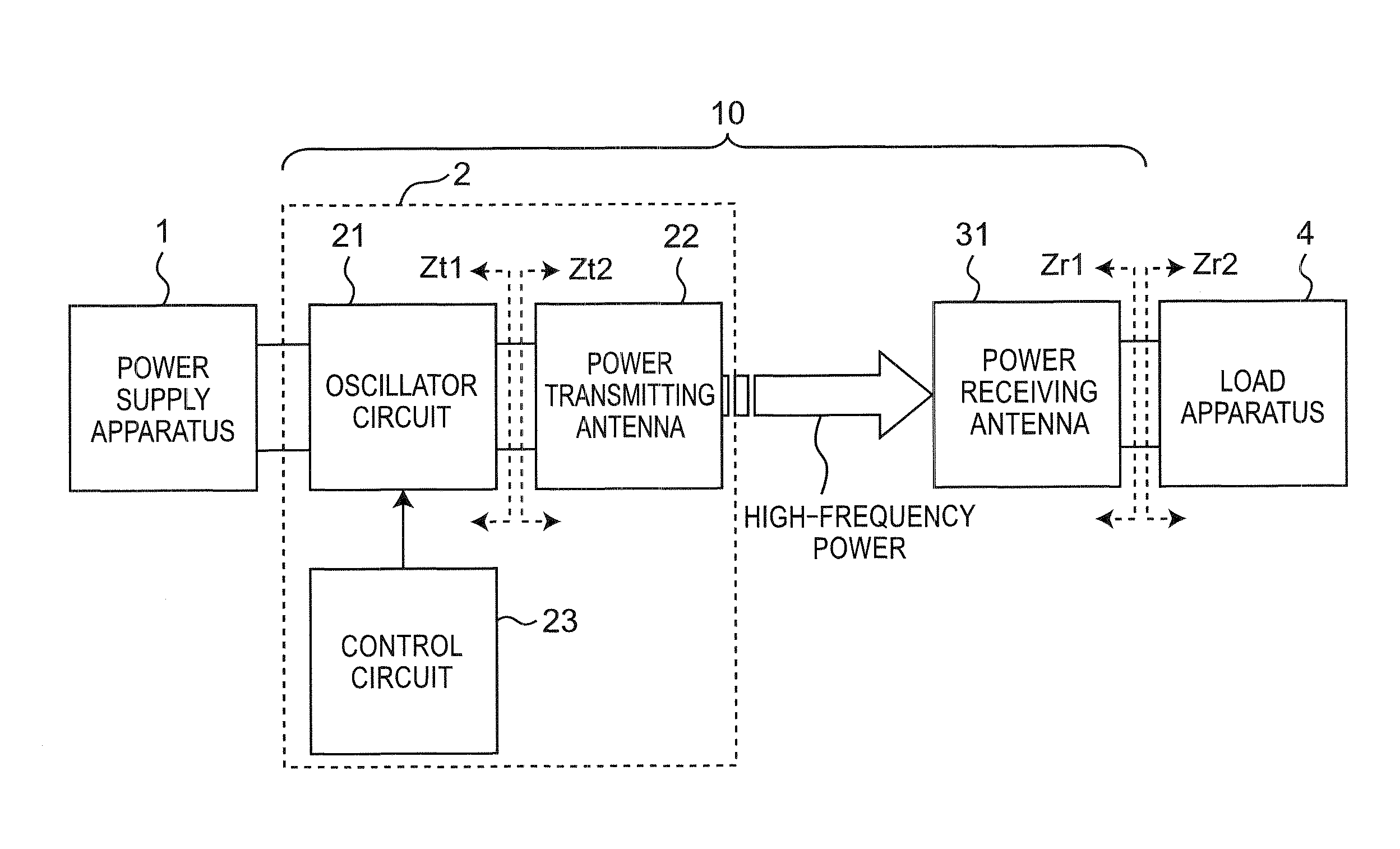
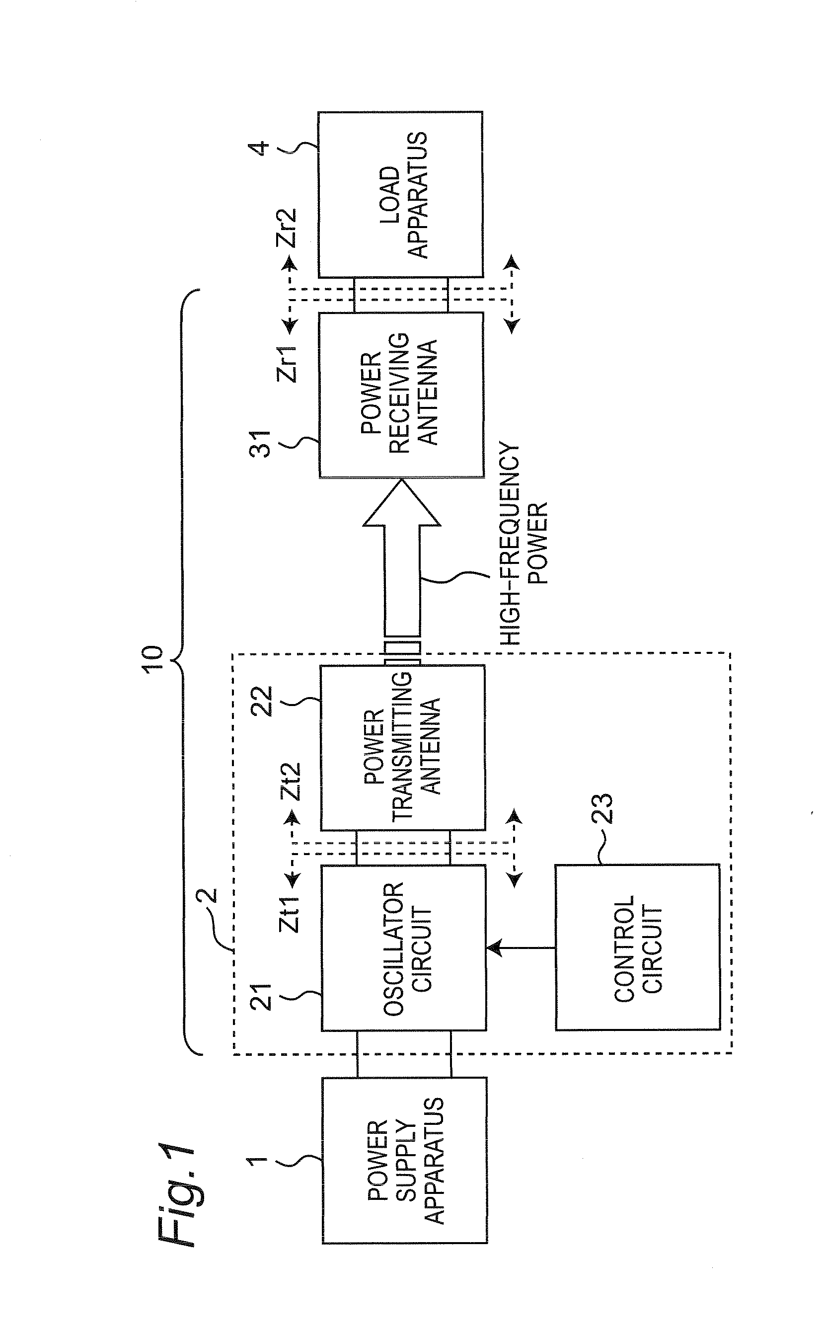
[0088]FIG. 1 is a block diagram showing a configuration of a wireless power transmission system 10 according to a first embodiment. The wireless power transmission system 10 includes: a wireless power transmitting apparatus 2 connected to a power supply apparatus 1; and a power receiving antenna 31 connected to a load apparatus 4. The wireless power transmission system 10 wirelessly transmits high-frequency power from a power transmitting antenna 22 of the wireless power transmitting apparatus 2 to the power receiving antenna.

[0089]The power supply apparatus 1 converts alternating-current power from a commercial alternating-current power supply, into direct-current power, and outputs the direct-current power to the wireless power transmission system 10. Alternatively, the power supply apparatus 1 converts the voltage of direct-current power from a direct-current power supply such as a battery, and outputs the power to the wireless power transmitting apparatus 2. The wireless power t...

second embodiment

[0151]FIG. 24 is a block diagram showing a schematic configuration of a wireless power transmission system 10A according to a second embodiment. The wireless power transmission system 10A includes: a wireless power transmitting apparatus 2A connected to the power supply apparatus 1; and a wireless power receiving apparatus 3A connected to the load apparatus 4. The wireless power transmission system 10A wirelessly transmits high-frequency power from the wireless power transmitting apparatus 2A to the wireless power receiving apparatus 3A.

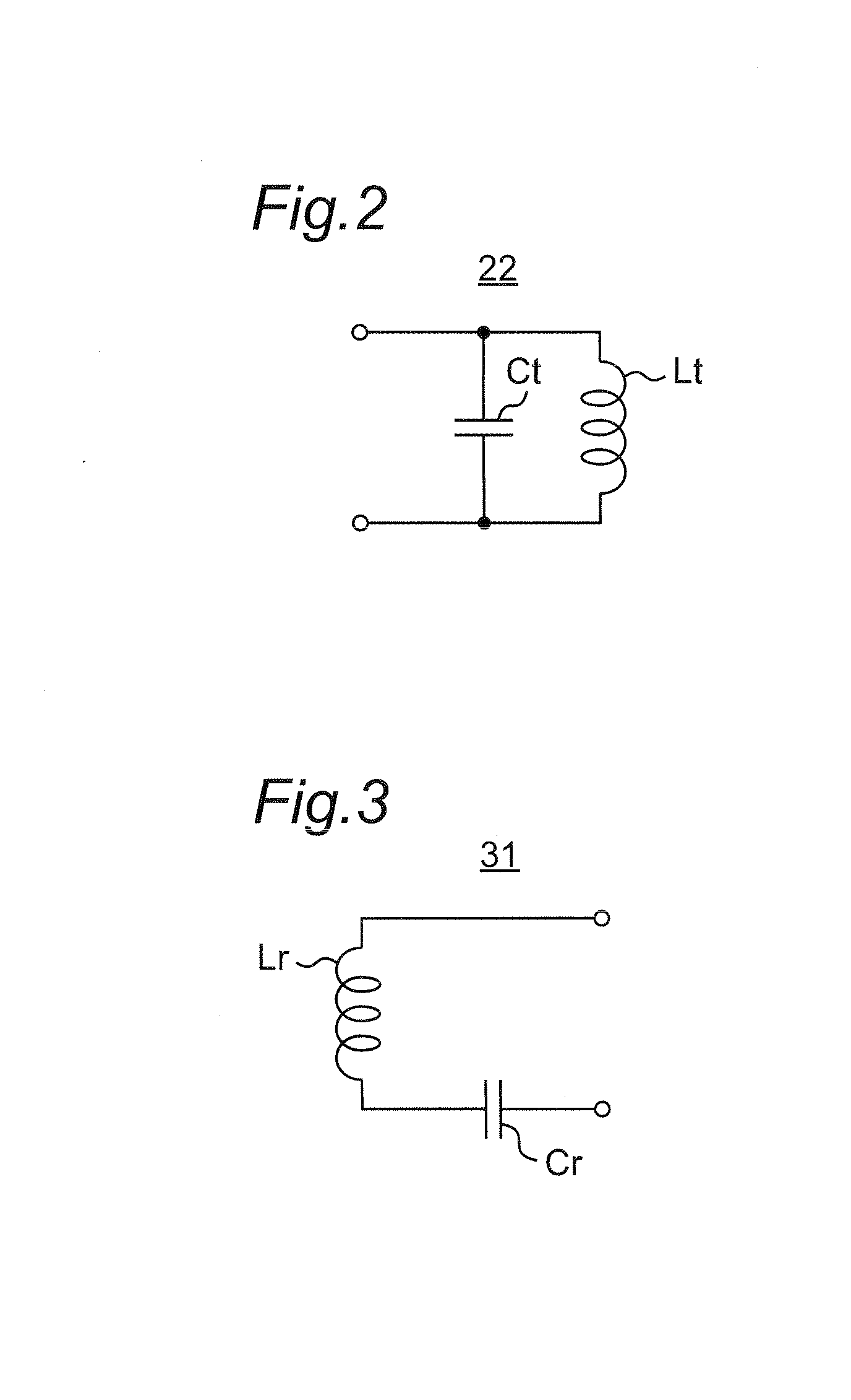
[0152]The wireless power transmitting apparatus 2A is provided with a power transmitting circuit 21A, the power transmitting antenna 22, a control circuit 23A, and the sensor 24. The power transmitting antenna 22 of the wireless power transmitting apparatus 2A is configured in a manner similar to that of the power transmitting antenna 22 of FIG. 2 or the power transmitting antenna 22a of FIG. 4. The power transmitting circuit 21A is connected to the ...

third embodiment

[0184]FIG. 38 is a block diagram showing a configuration of a wireless power transmission system 10B according to a third embodiment. The wireless power transmission system 10B includes: a wireless power transmitting apparatus 2B connected to the power supply apparatus 1; and a wireless power receiving apparatus 3B connected to the load apparatus 4. The wireless power transmission system 10B wirelessly transmits high-frequency power from the wireless power transmitting apparatus 2B to the wireless power receiving apparatus 3B.

[0185]Referring to FIG. 38, the wireless power transmitting apparatus 2B is provided with an oscillator circuit 21B, a power transmitting antenna 22B, and a control circuit 23B. The oscillator circuit 21B operates as a power transmitting circuit for generating high-frequency power from inputted direct-current power, and outputting the high-frequency power to the power transmitting antenna 22B. The oscillator circuit 21B is provided with: a pulse generator for g...


PUM


Abstract

A power transmitting antenna includes a first resonant circuit including a power transmitting coil, a power receiving antenna includes a second resonant circuit including a power receiving coil. When the power transmitting antenna and the power receiving antenna are electromagnetically coupled to each other, the power transmitting antenna and the power receiving antenna have an odd-mode resonance frequency corresponding to an odd-mode resonant condition, and an even-mode resonance frequency corresponding to an even-mode resonant condition, and the even-mode resonance frequency is higher than the odd-mode resonance frequency. A wireless power transmitting apparatus is provided with a power transmitting circuit configured to generate high-frequency power at a variable frequency, and supply the high-frequency power to the power transmitting antenna. A control circuit sets the frequency of the high-frequency power generated by the power transmitting circuit to one of the odd-mode resonance frequency and the even-mode resonance frequency.

Description

BACKGROUND OF THE INVENTION[0001]1. Field of the Invention[0002]The present disclosure relates to a wireless power transmission system for wirelessly and contactlessly transmitting power using resonant magnetic coupling. The present disclosure also relates to a wireless power transmitting apparatus and a wireless power receiving apparatus which are used in the wireless power transmission system, and relates to control circuits of the wireless power transmitting apparatus and the wireless power receiving apparatus.[0003]2. Description of Related Art[0004]U.S. Patent Application Publication No. 2008 / 0278264 (FIGS. 12 and 14) discloses a wireless power transmission apparatus for transmitting energy through space between two resonant circuits. The wireless power transmission apparatus wirelessly (contactlessly) transmits oscillating energy by coupling two resonant circuits through leakage of oscillating energy at a resonance frequency (evanescent tail) generated in space around the reso...

Claims


Application Information

Patent Timeline
IPC IPC(8): H01F38/14
CPCB60L2200/12B60L2210/10B60L2210/30B60L2210/40B60L2240/36Y02T90/12Y02T90/14H02J50/90B60L50/20B60L53/36B60L53/51H02J7/35B60L53/124Y02T10/72Y02T10/7072Y02T10/70H02J50/20H02J50/80H02J50/12H02J50/60H01F38/14
Inventor KANNO, HIROSHIASANUMA, KENICHI
Owner PANASONIC INTELLECTUAL PROPERTY MANAGEMENT CO LTD
Why Eureka
Try Eureka