Spark plug for internal combustion engines

a technology for spark plugs and internal combustion engines, which is applied in the direction of spark plugs, basic electric elements, electric devices, etc., can solve the problems of affecting the stability of combustion, and affecting the ignitability of spark plugs, so as to prevent the stagnation of airflow f, stable ignitability, and the effect of reducing the stagnation ra

Active Publication Date: 2014-06-12
DENSO CORP
View PDF6 Cites 7 Cited by
  • Summary
  • Abstract
  • Description
  • Claims
  • Application Information

AI Technical Summary

Benefits of technology

[0096]The advantageous effects of the present embodiment will be described below.
[0097]The spark plug 1 has the opposite projection 23, the electrode-side baffle projection 22 and the opposite-side baffle projection 24. Being provided with these projections, an airflow (flow of air-fuel mixture) that occurs in the combustion chamber and is directed to the spark discharge gap G will be prevented from being blocked, in whatever posture the spark plug 1 may be mounted with respect to the internal combustion engine.
[0098]FIG. 4 shows a state where a part of the ground electrode 5 (vertical portion 51) is located upstream of the spark discharge gap G. FIG. 5 is a cross-sectional view taken along the line V-V of FIG. 4. As shown In FIGS. 4 and 5, when a part of the ground electrode 5 is located upstream of the spark discharge gap G, an airflow (flow of air-fuel mixture) F that has passed by the side of the ground electrode 5 from the upstream is directed to the spark discharge gap G by the electrode-side baffle projection 22. More specifically, the electrode-side baffle projection 22 serves as a guide for the airflow F and directs the airflow F to the spark discharge gap G. Accordingly, stagnation of the airflow F is prevented in the vicinity of the spark discharge gap G. As a result, a discharge spark S is extended to a large extent and stable ignitability is ensured in the spark plug 1, In FIGS. 4 and 5, the area indicated by a reference Z shows stagnation of the airflow F. The same applies to other figures.
[0099]FIG. 6 shows a state where a portion of the ground electrode 5 (vertical portion 51) is located downstream of the spark discharge gap G. FIG. 7 is a cross-sectional view taken along the line VII-VII of FIG. 6. As shown in FIGS. 6 and 7, when a portion of the ground electrode 5 is located downstream of the spark discharge gap G, the oppos

Problems solved by technology

As a result, the ignitability of the spark plug may be impaired.
In other words, depending on the mounting posture of the spark plug with respect to the internal combustion engine, the ignitability of the spark plug may be problematically varied.
In such an internal combustion engine, combustion stability may be impaired depending on the mounting posture of the spark plug.
Further, it is difficult to control the mounting posture of the spark plug with respect to the internal combustion engine, i.e. to control the position of the ground electrode in the circumferential direction of the spark plug.
This is because the mounting posture of the spark plug is unavoidably varied, depending such as on the state of the mounting screws formed in the housing, or the degree of tightening the spark plug in the work of mounting the spark plug on the internal combustion engine.
However, the “configuration in which the ground electrode is drilled to form

Method used


Image

  • Spark plug for internal combustion engines
  • Spark plug for internal combustion engines
  • Spark plug for internal combustion engines

Examples


first embodiment

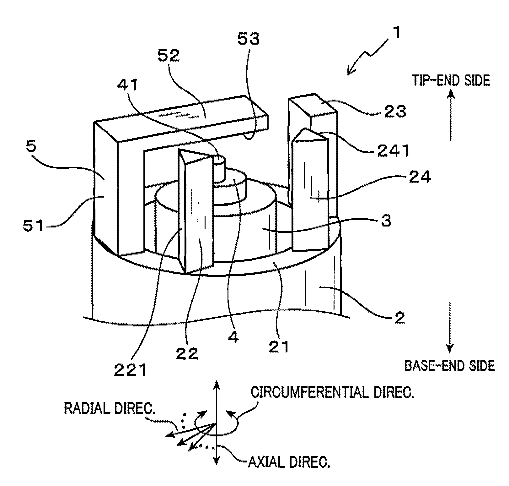
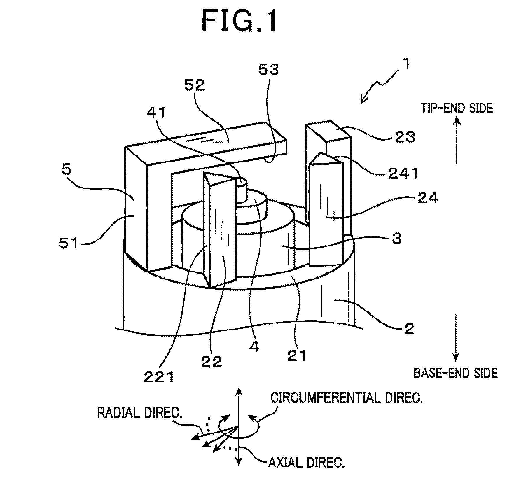
[0077]Referring to FIGS. 1 to 7, hereinafter is described a first embodiment of a spark plug 1 for an internal combustion engine of the present invention.

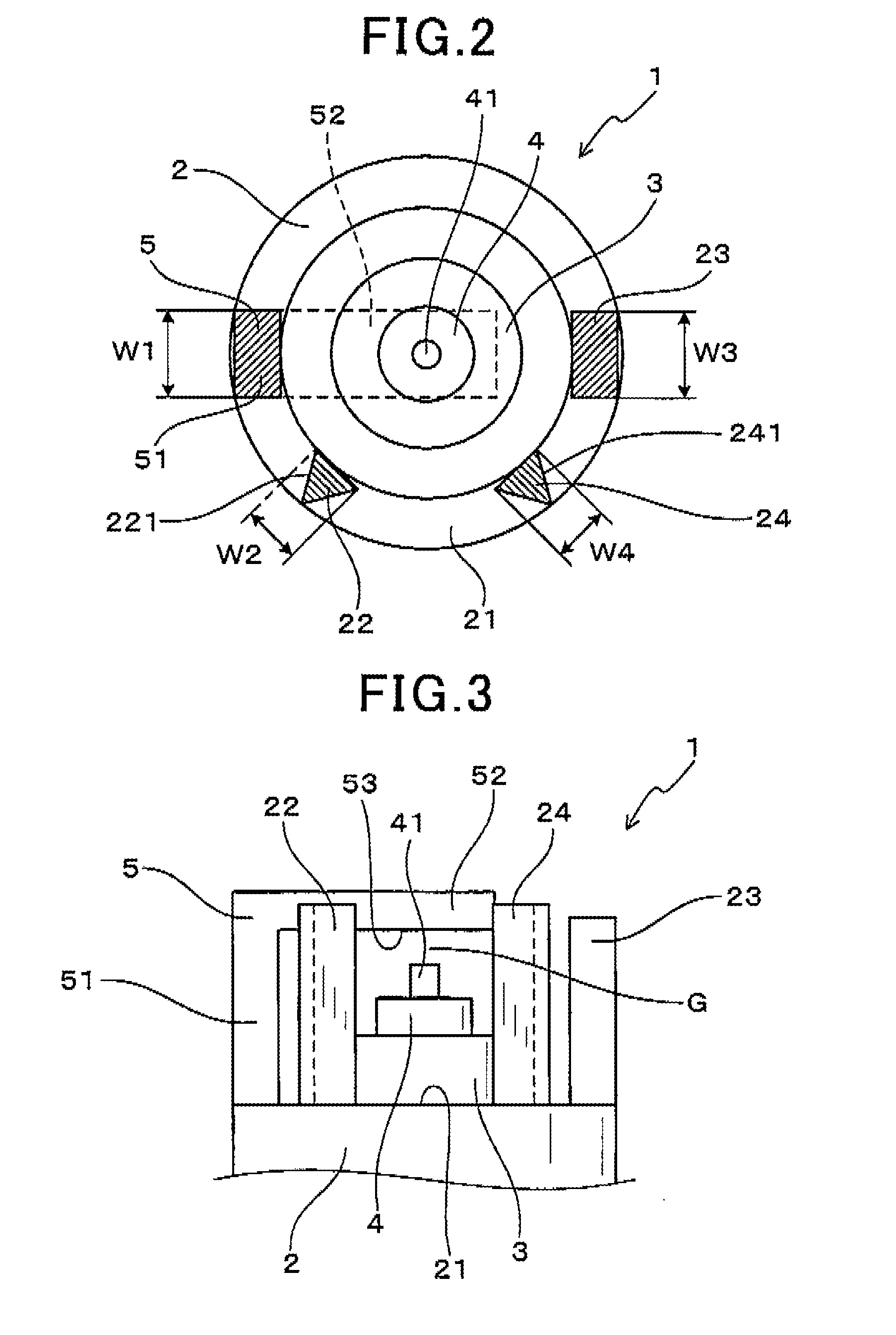
[0078]As shown in FIGS. 1 to 3, the spark plug 1 of the first embodiment includes a cylindrical housing 2, an insulation porcelain 3 held inside the housing 2, and a center electrode 4 held inside the insulation porcelain 3 such that a top end portion of the center electrode 4 is projected out of the insulation porcelain 3. Further, the spark plug 1 includes a ground electrode 5 that is projected out of a top end portion 21 of the housing 2 toward a tip-end side. A spark discharge gap G is formed between the center electrode 4 and the ground electrode 5.

[0079]As shown in FIGS. 1 and 3, the ground electrode 5 includes a vertical portion 51 and an opposing portion 52. The vertical portion 51 stands upright from the top end portion 21 of the housing 2. The opposing portion 52 is provided by bending an end of the vertical portion 51 to...

experimental example 1

[0122]As shown in FIG. 13, in Experimental Example 1, the spark plugs 1, 9 and 90 of the first embodiment, Comparative Example 1 and Comparative Example 2, respectively, were used to investigate how the A / F limit varied depending on the location of the vertical portions 51 and 951 of the ground electrodes 5 and 95, respectively, with respect to the airflow F.

[0123]Specifically, the A / F limit was measured by changing a mounting angle β in increments of 90° in a range of 0° to 360°. The mounting angle β is an angle between the direction of entry of the airflow F into the spark plug 1 and the radial direction connecting between the circumferential position of the vertical portion 51 of the ground electrode 5 and the center axis of the spark plug 1, when the spark plug 1 of the first embodiment is viewed in the axial direction from the tip-end side. More specifically, when the mounting angle β is 0°, the vertical portion 51 of the ground electrode 5 is located upstream of the spark disc...

second embodiment

[0132]Referring to FIGS. 15 and 16, hereinafter is described a second embodiment of the present invention. In the second and the subsequent embodiments, the components identical with or similar to those in the first embodiment are given the same reference numerals for the sake of omitting unnecessary explanation.

[0133]As shown in FIGS. 15 and 16, the spark plug 1 of the second embodiment includes the electrode-side baffle projection 22 and the opposite-side baffle projection 24, which are both formed into a quadratic prism.

[0134]The electrode-side and opposite-side baffle projections 22 and 24 have cross sections at a position axially nearest to the spark discharge gap G, in which radial widths W20 and W40 are larger than the circumferential widths W2 and W4, respectively, the cross sections being perpendicular to the axial direction. In the present embodiment, similar to the first embodiment, the electrode-side and opposite-side baffle projections 22 and 24 have top ends which are ...


PUM


Abstract

A spark plug for internal combustion engines is provided, where the spark plug includes a cylindrical housing, a cylindrical insulation porcelain part, a center electrode, and a ground electrode. The insulation porcelain is housed in the housing and the center electrode is held inside the insulation porcelain. The ground electrode protrudes from a top end portion of the housing. A spark discharge gap is left between the ground and center electrodes. Further, first to third projections are formed on the top end portion. The first projection is opposed to the ground electrode with the center electrode therebetween. The second projection is closer to the ground electrode than to the first projection. The third projection is closer to the first projection than to the ground electrode.

Description

CROSS-REFERENCE TO RELATED APPLICATION[0001]This application is based on and claims the benefit of priority from earlier Japanese Patent Application No. 2012-269106 filed Dec. 10, 2012, the description of which is incorporated herein by reference.BACKGROUND OF THE INVENTION[0002]1. Technical Field of the Invention[0003]The present invention relates to a spark plug for internal combustion engines which are mounted in structures such as vehicles.[0004]2. Related Art[0005]Spark plugs are used as igniting means in internal combustion engines, such as the engines for vehicles. Some of such spark plugs have a configuration in which a center electrode is permitted to axially face a ground electrode to form a spark discharge gap therebetween. This type of spark plug causes discharge in the spark discharge gap to use the discharge for the ignition of the air-fuel mixture in the combustion chamber.[0006]In the combustion chamber, a flow of the air-fuel mixture, such as a swirl flow or a tumbl...

Claims


Application Information

Patent Timeline
IPC IPC(8): H01T13/02
CPCH01T13/02H01T13/32
Inventor SHIBATA, MASAMICHIINOHARA, TAKAYUKIOKABE, SHINICHIAOCHI, TAKANOBUDOI, KAORI
Owner DENSO CORP
Why Eureka
Try Eureka