

Multi-stage quick charging system
a charging system and multi-stage technology, applied in the direction of electrical storage system, battery/fuel cell control arrangement, propulsion by batteries/cells, etc., can solve the problems of system cost and even possible energy loss of the whole, limited or expensive connection points compatible with the electrical network, and affecting the quality of the electric wave of the network
- Summary
- Abstract
- Description
- Claims
- Application Information
AI Technical Summary
Benefits of technology
Problems solved by technology
Method used
Image

Examples
Embodiment Construction
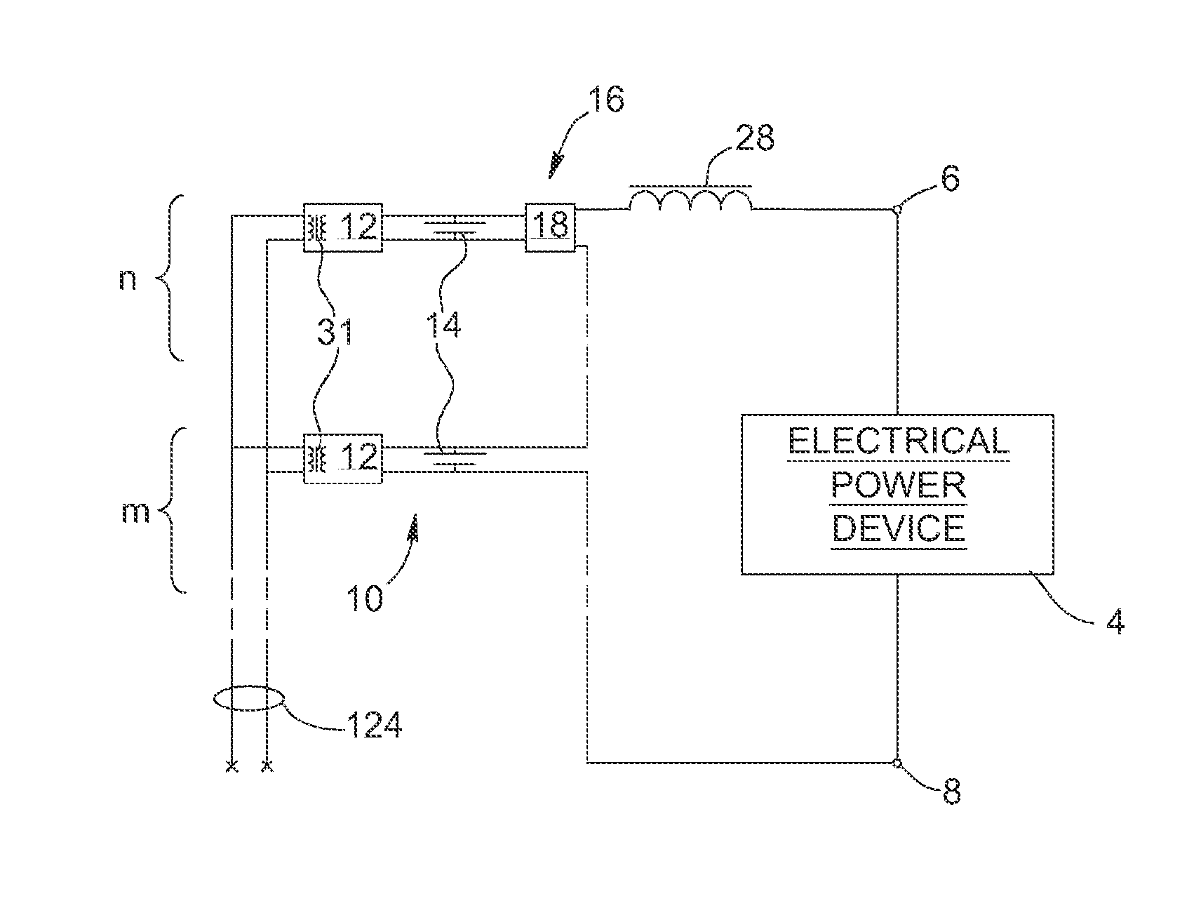
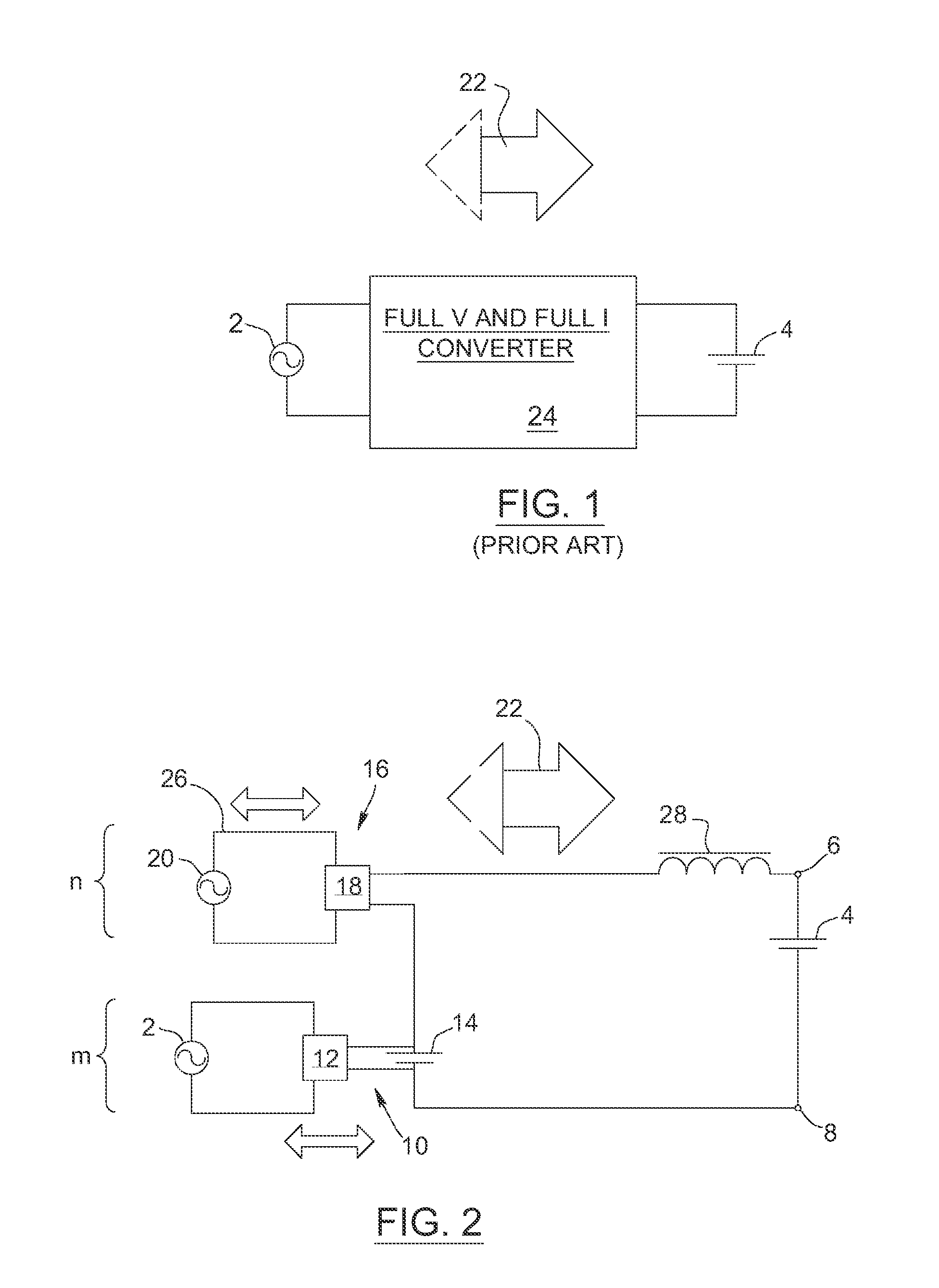
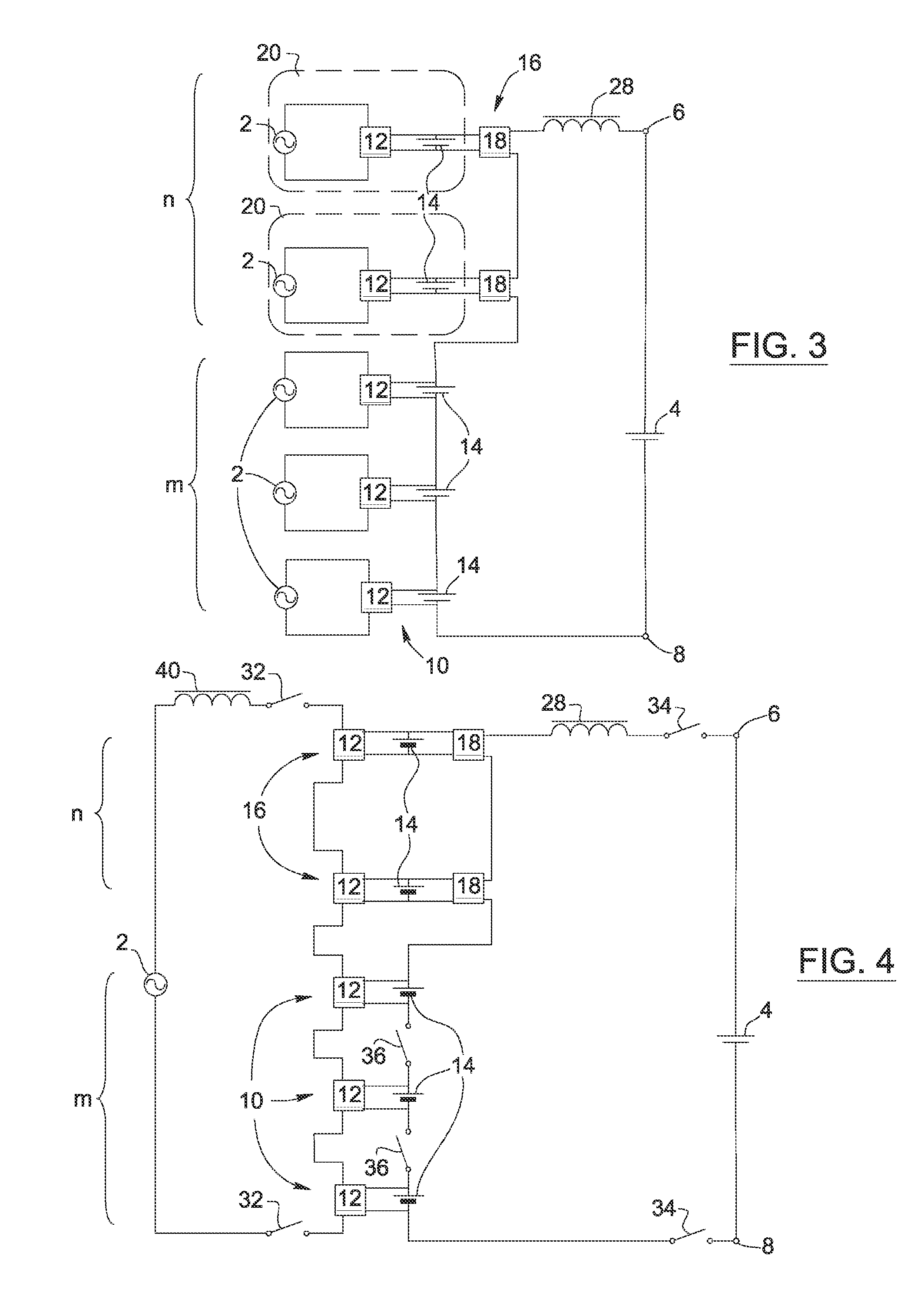
[0041]Referring to FIG. 2, there is shown a multi-stage quick charging system for exchanging energy with an electrical power device 4 such as a power battery of an electric vehicle in the case illustrated in FIG. 2. The quick charging system has terminals 6, 8 for connection with the electrical power device 4. A number n of converter stages 16 and a number m of energy internal storage stages 10 are connected in series between the terminals 6, 8, with n≧1, m≧0 and n+m≧2. Each converter stage 16 has a power converter 18 coupled to an arrangement having an intermediate power battery module 14 (as shown e.g. in FIG. 18) and / or a connection 26 to an electrical supply source 20 connected or not to an electrical network 2 in the case illustrated in FIG. 2. Each energy internal storage stage 10 has an intermediate power battery module 14. Each intermediate power battery module 14 is characterized by a high no-load voltage with respect to voltage drops caused by internal impedances (not show...
PUM
 Abstract
Description
Claims
Application Information