Current Detecting Circuit, Temperature Compensating Device and Display Device

a current detection and display device technology, applied in the field of display technology, can solve the problems of display panel flicker, display panel may not display normally, display panel flicker is likely to occur in the display panel, etc., and it is difficult for the temperature compensating device to accurately correct the deviation in turn-on voltag

Active Publication Date: 2014-06-12
BOE TECH GRP CO LTD +1
View PDF9 Cites 10 Cited by
  • Summary
  • Abstract
  • Description
  • Claims
  • Application Information

AI Technical Summary

Benefits of technology

[0030]The invention provides a current detecting circuit, a temperature compensating device and a display device. If the current detecting circuit is used in a display panel, it can used to reflect change in temperature of the display panel. The temperature compensating device can detect the change in temperature of the display panel through the current detecting circuit, calculates a corrected voltage value, then controls the gate driving circuit to output a corrected voltage by means of the control chip, so that an object of correcting the turn-on voltage of the driving thin film transistor in the display panel can be realized.

Problems solved by technology

In the prior art, as the voltage supplied to the gate from a gate driving circuit is constant, image flicker is likely to occur in the display panel or the display panel may not display normally.
Also, the result of the thermistor is affected by the manufacturing process, thus it is difficult for the temperature compensating device to accurately correct the deviation in turn-on voltage of the thin film transistor due to changes in temperature.

Method used


Image

  • Current Detecting Circuit, Temperature Compensating Device and Display Device
  • Current Detecting Circuit, Temperature Compensating Device and Display Device
  • Current Detecting Circuit, Temperature Compensating Device and Display Device

Examples


Embodiment Construction

[0036]Hereinafter, the solutions in the invention will be described clearly and completely with reference to drawings. It is apparent that the described embodiments just some but not all of the embodiments of the invention.

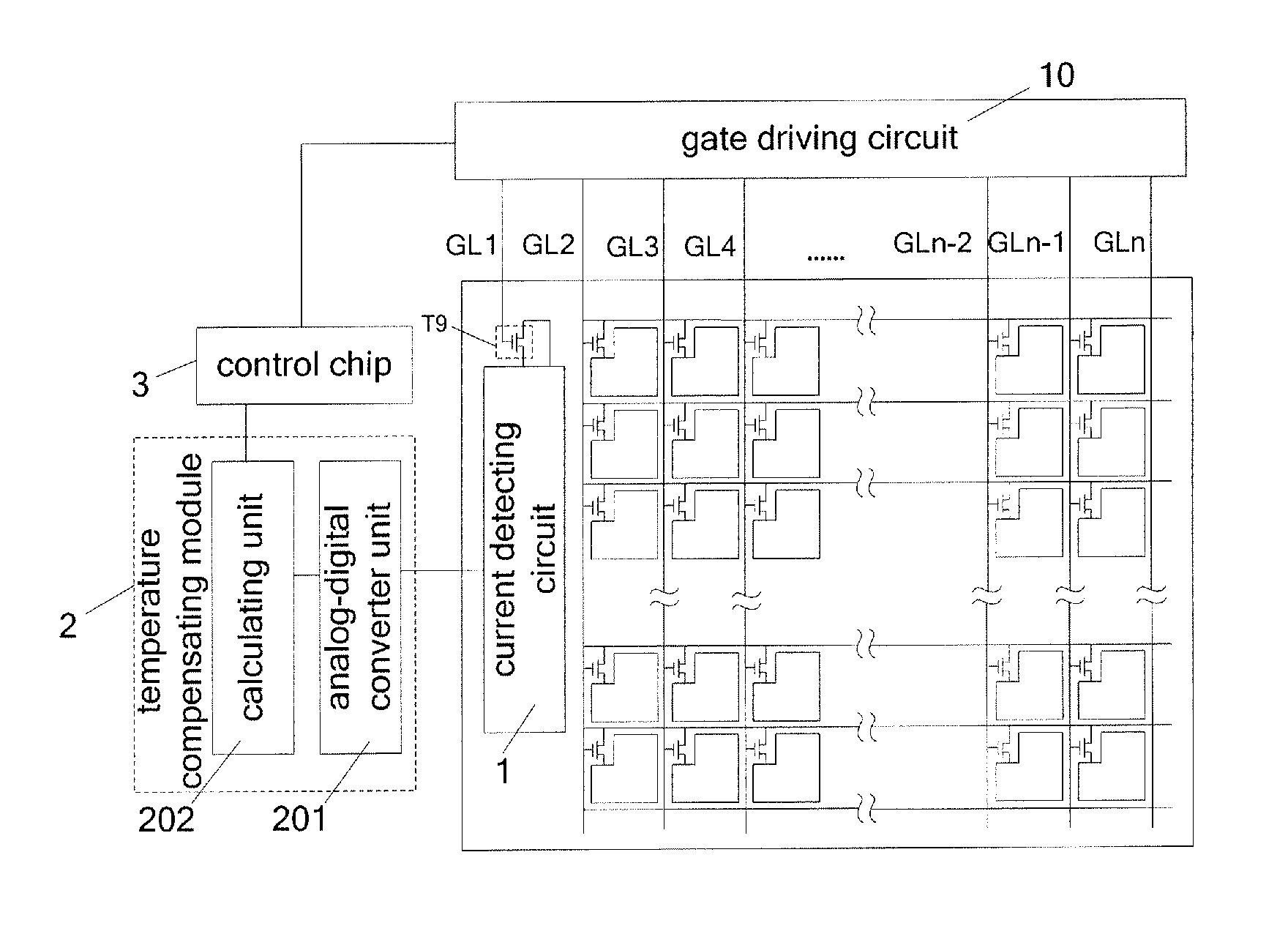
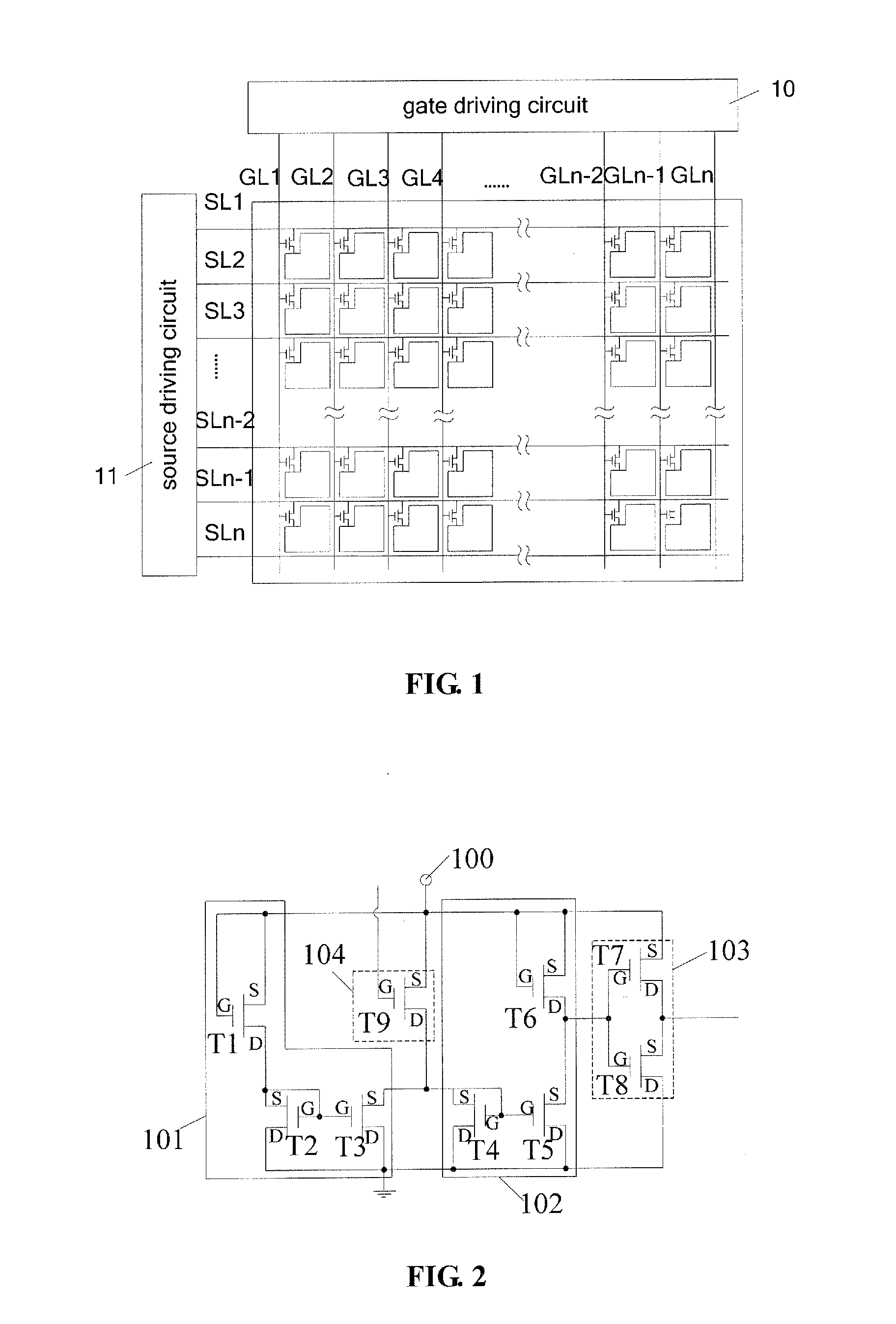
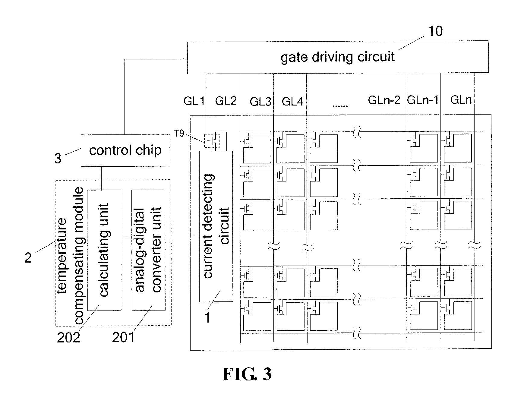
[0037]As shown in FIG. 2, an embodiment in the invention provides a current detecting circuit for detecting the current of a unit to be detected, which comprises a voltage source 100, a first mirror current source 101, a second mirror current source 102 and an inverter 103, wherein

[0038]the first mirror current source 101 is configured to provide a reference current, and includes an input terminal, an output terminal and a ground terminal, wherein the input terminal is electrically connected to the voltage source 100, and the output terminal is electrically connected to the second mirror current source 102;

[0039]the second mirror current source 102 is configured to obtain a difference between a current output from the first mirror current source 101 and a current ...


PUM


Abstract

The invention discloses a current detecting circuit, a temperature compensating device and a display device, and relates to the field of display technology, which resolves the problem of image flicker in the display screen or abnormal display due to changes in the turn-on voltage of the thin film transistors in the display panel caused by changes in the temperature in the prior art. The current detecting circuit includes a voltage source, a first mirror current source for supplying a reference current, a second mirror current source for obtaining a difference between a current output from the first mirror current source and a current output from a unit to be detected and converting the difference into a voltage signal, and an inverter for amplifying the voltage signal and output a detection result. A temperature compensating device including the foregoing current detecting circuit. A display device including the above temperature compensating device.

Description

FIELD OF THE INVENTION[0001]The present invention relates to the field of display technology, and particularly to a current detecting circuit, a temperature compensating device and a display device.BACKGROUND OF THE INVENTION[0002]A liquid crystal display (LCD) device uses a LCD panel to display images. As shown in FIG. 1, a display panel in the prior art includes a display area and a to non-display area. In the display area, there are provided gate lines (GL1-GLn), data lines (DL1-DLn), and a plurality of pixel units in array arrangement defined by GL (Gate Line) and DL (Data Line). Each pixel unit includes a thin film transistor (TFT) and a pixel electrode, the thin film transistor includes a gate (G), a source (S) and a drain (D), wherein the gate G is connected to gate line GL, the source S is connected to the data line DL, and the drain D is connected to the pixel electrode. In the non-display area, there are provided a gate driving circuit 10 and a source driving circuit 11, t...

Claims


Application Information

Patent Timeline
Patent Type & Authority Applications(United States)
IPC IPC(8): G09G3/36G01R19/32
CPCG01R19/32G09G3/3611G01R19/0092G09G3/3648G09G2320/041
Inventor HUANG, SHANSHANWANG, MINNIE, CHUNYANG
Owner BOE TECH GRP CO LTD
Why Eureka
Try Eureka