Lighting device for vehicles

Inactive Publication Date: 2014-06-12
HELLA KGAA HUECK & CO
View PDF4 Cites 18 Cited by
  • Summary
  • Abstract
  • Description
  • Claims
  • Application Information

AI Technical Summary

Benefits of technology

[0006]The special advantage of the invention consists in that, through the arrangement of scattering elements in the area of a gap between a first lamp unit and a second lamp unit, light is deflected or scattered so that the gap itself is illuminated by a side light beam. The scattering elements have the effect that the side light beam runs in the direction of the gap between the two lamp units and can be output there. In this way, the two illuminating lenses of the adjacent lamp units are visually “connected” to each other by the emission of the side light beam in the gap. The scattering element can be an integral part of the lens and/or of an additional light guiding part that is arranged within a housing of the first lamp unit and/or the second lamp unit. The invention makes it possible that the gap is perceived as an illuminated area even at a relatively acute observation angle relative to an optical axis of the lamp units or relative to the longitudinal axis of a vehicle. Here, the invention takes advantage of the fact that an observer never views the first lamp unit and the second lamp unit from the same observation angle.
[0007]According to one preferred embodiment of the invention, the light guiding part is constructed as a flat or rod-shaped light conductor in which a side surface is provided with the scattering element on a side facing the gap. Additionally or alternatively, an additional diffusing lens can be arranged between the light conductor or another lamp unit of the lighting device on one side and a side section of the lens on the other side. Such an additional diffusing lens is useful especially when the light conductor is constructed without optical elements

Problems solved by technology

If the first lamp unit and the second lamp unit are located on the rear side of a vehicle, wherein transparent lenses of the first lamp unit and the second lamp unit are essentially perpendicular to the longitudinal axis of the vehicle, then this produces the problem that, due to the necessary spacing

Method used


Image

  • Lighting device for vehicles
  • Lighting device for vehicles
  • Lighting device for vehicles

Examples


Embodiment Construction

[0019]In the following detailed description numerous specific details are set forth in order to provide a thorough understanding of the invention. However, it will be understood by those skilled in the art that the present invention may be practiced without these specific details. For example, the invention is not limited in scope to the particular type of industry application depicted in the figures. In other instances, well-known methods, procedures, and components have not been described in detail so as not to obscure the present invention.

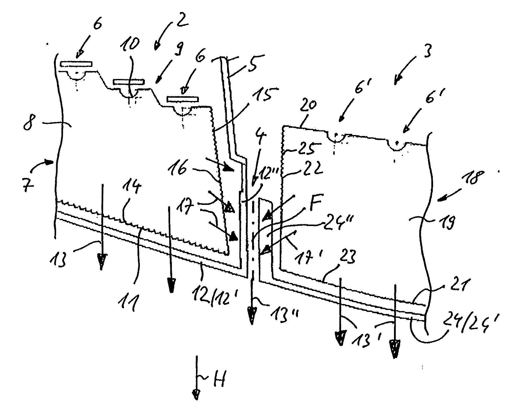
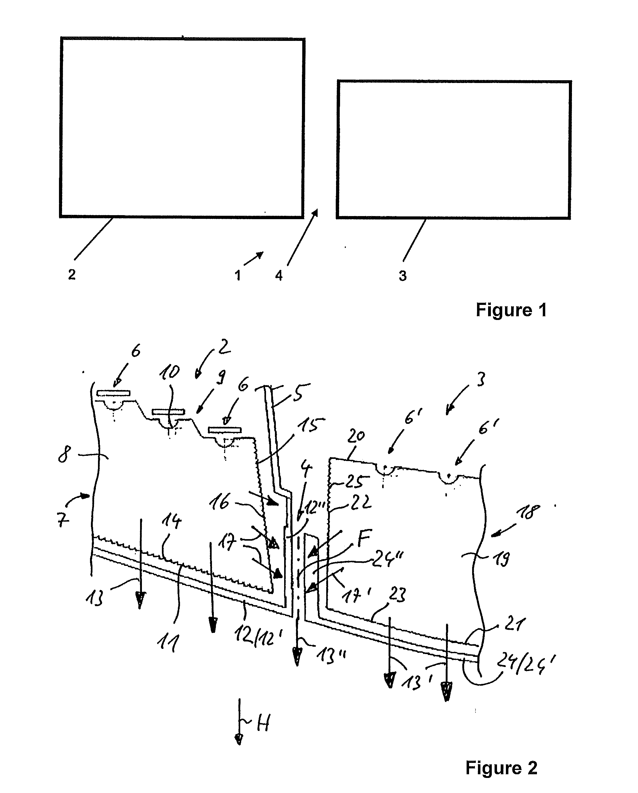
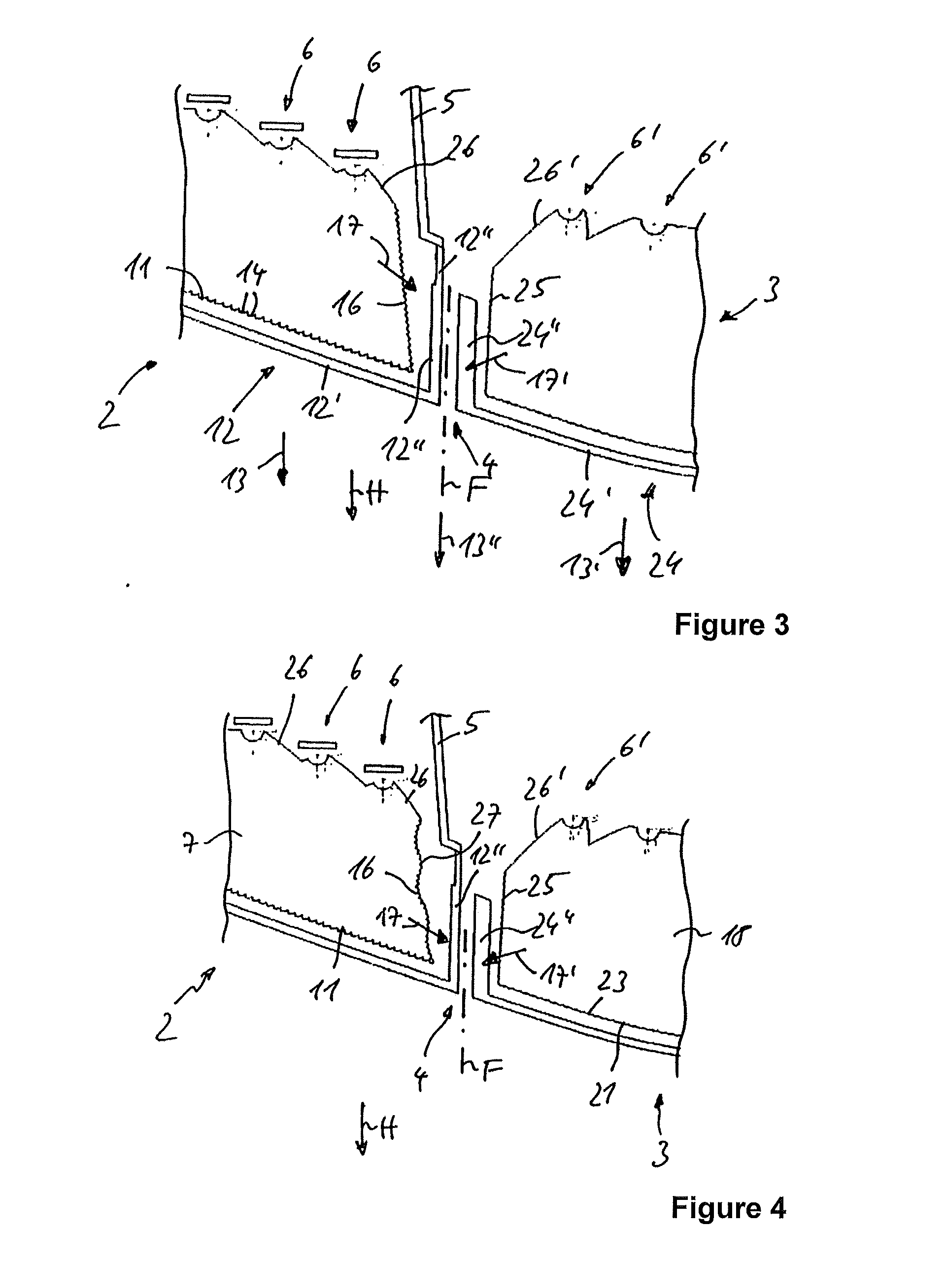
[0020]The invention relates to a lighting device 1 for vehicles that is advantageously constructed as a two-part rear lamp and is used for generating a tail lamp, brake light, or turn signal function. Alternatively, the lighting device according to the invention can also be arranged in a front area of a motor vehicle.

[0021]The two-part rear lamp 1 has a first lamp unit 2 that is mounted on a stationary first body part of the motor vehicle, for ...


PUM


Abstract

A lighting device includes a first lamp unit mountable on a first body part and a second lamp unit mountable on a second body part and movable relative to the first body part, wherein a gap is formed between the first and second lamp units, the first and second lamp units each have a housing with light sources and covered by a transparent lens, wherein the lens has a base surface for transmitting a functional light beam in the main beam direction and a side section that borders the gap and runs parallel to a gap plane and through which a side light beam enters into the gap, wherein the side section of the lens and/or a light guiding part covered by the lens has scattering elements, so that the side light beam emitted by the light source can be emitted along the gap plane in the main beam direction.

Description

CROSS REFERENCE[0001]This application claims priority to German Patent Application No. 10 2012 112075.7, filed Dec. 11, 2012.TECHNICAL FIELD OF THE INVENTION[0002]The invention relates to a lighting device for vehicles with a first lamp unit that can be mounted on a first body part and with a second lamp unit that can be mounted on a second body part that can move relative to the first body part, wherein a gap is formed between the first lamp unit and the second lamp unit, the first lamp unit and the second lamp unit each have a housing with a number of light sources, and each housing is covered by a transparent lens, wherein the lens has a base surface covering the housing for transmitting a functional light beam in the main beam direction and a side section that borders the gap and runs parallel to a gap plane and through which a side light beam emitted from the light source enters into the gap.BACKGROUND OF THE INVENTION[0003]From DE 10 2004 043 045 A1, a lighting device for vehi...

Claims


Application Information

Patent Timeline
IPC IPC(8): F21S8/10F21W107/10
CPCF21S48/00B60Q1/0041F21S43/14F21S43/26F21S43/237F21S43/239F21S43/243F21S43/249F21S43/40B60Q1/304F21S43/00
Inventor MUGGE, MARTIN
Owner HELLA KGAA HUECK & CO
Why Eureka
Try Eureka