X-ray apparatus with deflectable electron beam

a technology of electron beam and x-ray apparatus, which is applied in the field of x-ray apparatus, can solve the problems of difficult in practice to align the x-ray optics with the focal spot of the x-ray source, and achieve the effect of simplifying the alignment of the x-ray optics with respect to the microfocus x-ray sour

Inactive Publication Date: 2014-06-12
BRUKER AXS
View PDF9 Cites 7 Cited by
  • Summary
  • Abstract
  • Description
  • Claims
  • Application Information

AI Technical Summary

Benefits of technology

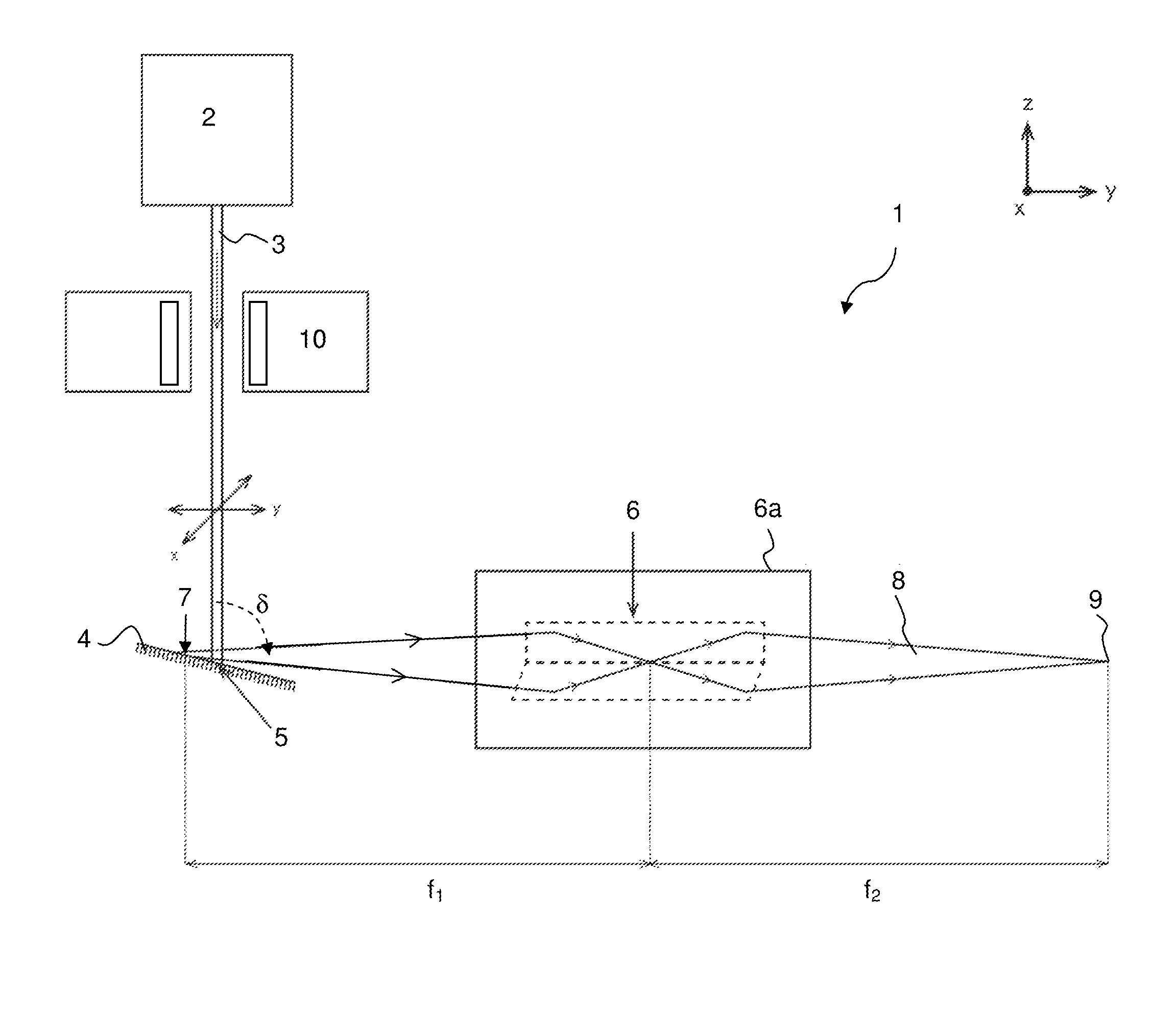
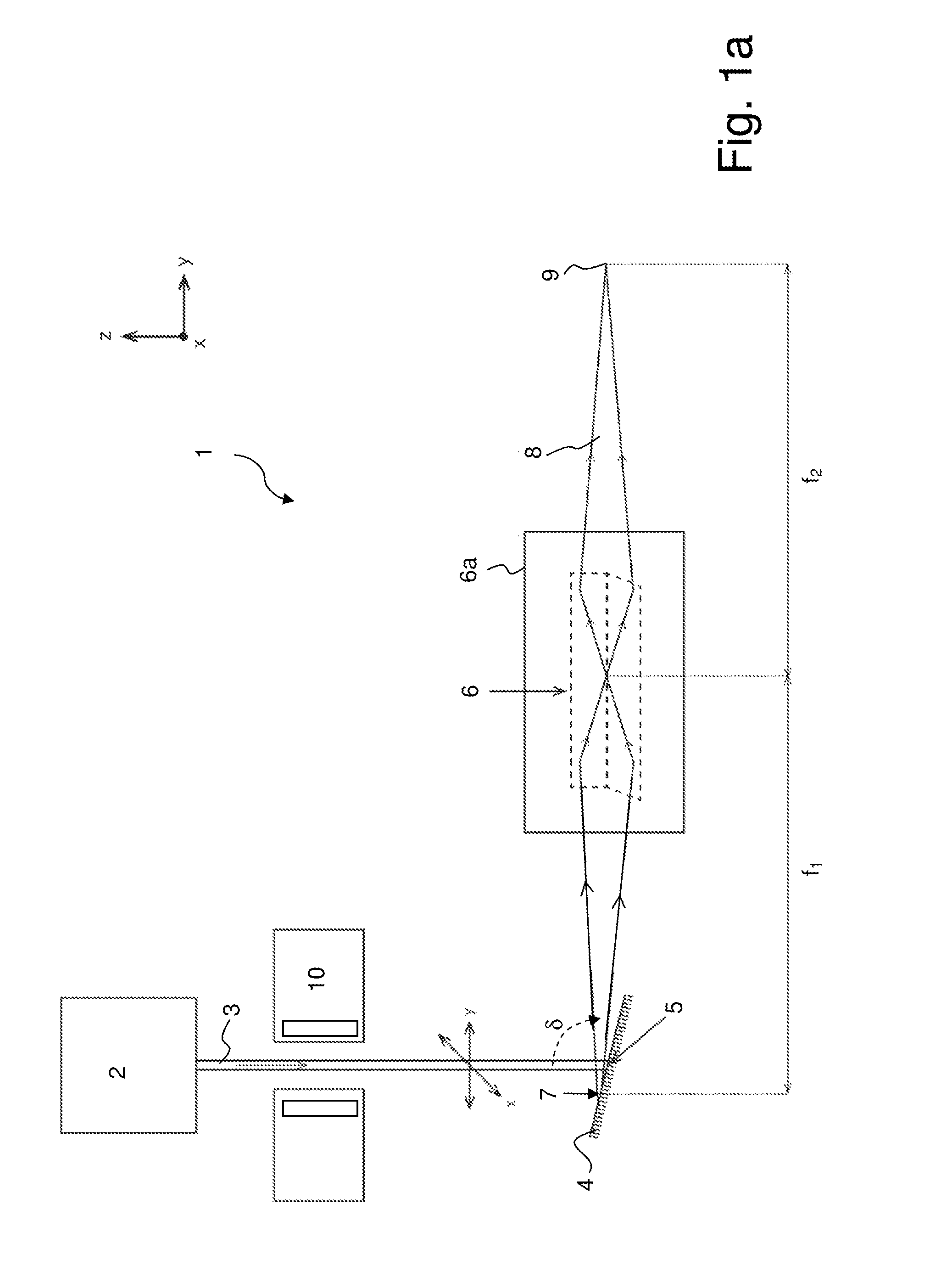
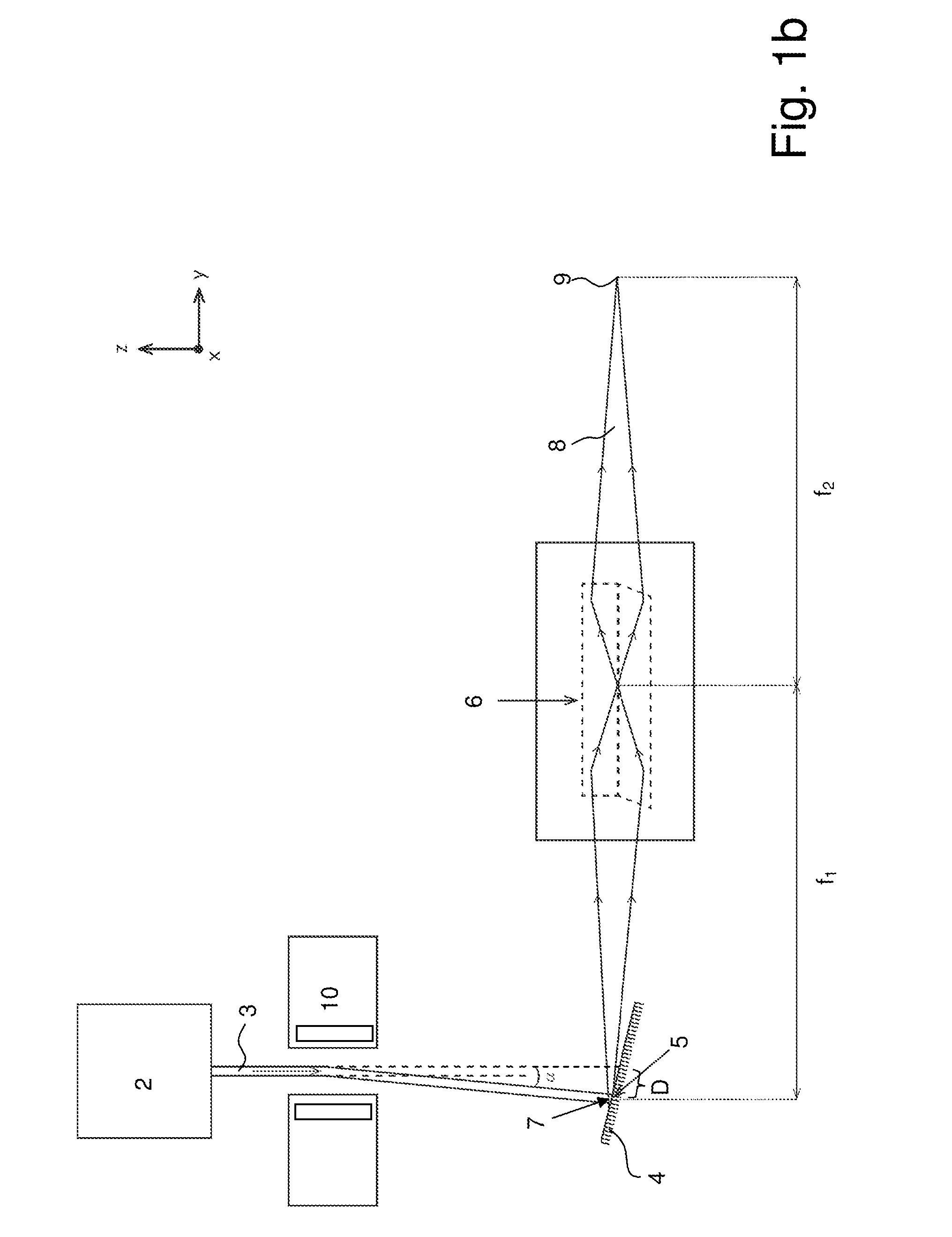
[0013]It is the object of the invention to provide an X-ray apparatus wherein aligning the X-ray optics with respect to a microfocus X-ray source is simplified.

Problems solved by technology

However, mechanically moving the X-ray optics on the μm range to match the focal spot of the X-ray source with the focus of the X-ray optics is difficult in practice, in particular due to backlash of alignment mechanics.

Method used


Image

  • X-ray apparatus with deflectable electron beam
  • X-ray apparatus with deflectable electron beam
  • X-ray apparatus with deflectable electron beam

Examples


Embodiment Construction

[0020]In a preferred embodiment of the inventive apparatus, the target is a liquid metal jet target. This allows a particularly high brilliance. The target material at the focal spot is continuously replaced, what avoids a local overheating (e.g. evaporation) of the target. Further, the jet is a simple way to provide a curved target surface (see below), typically with a circular curvature.

[0021]Preferred is a further development of this embodiment, wherein in a direction transverse to the liquid metal jet target propagation direction and transverse to the propagation direction of the electron beam, the extension of the focal spot is smaller at least by a factor FT, with FT=2, preferably FT=5, than the extension of the liquid metal jet target. This increases the available alignment range of the focal spot on the target. Further, a curvature of the target has a stronger effect on the apparent spot size and the self-absorption of the target.

[0022]In a highly particularly preferred embo...


PUM


Abstract

An x-ray apparatus (1), has an electron beam source (2), a target (4), onto which the electron beam (3) is directed to form a focal spot (5; 5a, 5b) on the target (4), x-ray optics (6) for collecting x-rays emitted from the focal spot (5; 5a, 5b) to form an x-ray beam (8) and a sample position (9) at which the x-ray beam (8) is directed. The x-ray apparatus (1) further includes an electrostatic or electromagnetic electron beam deflection device (10) suitable for moving the focal spot (5; 5a, 5b) on the target (4). The extension of the focal spot (5; 5a, 5b) in any direction (x, y, z) is at least a factor of 1.5 smaller than the extension of the target (4). An x-ray apparatus is thereby provided with simplified alignment of the x-ray optics with respect to a microfocus x-ray source.

Description

BACKGROUND OF THE INVENTION[0001]The invention relates to an X-ray apparatus, comprising[0002]an electron beam source, emitting an electron beam,[0003]a target, onto which the electron beam is directed, thus forming a focal spot on the target,[0004]X-ray optics, collecting X-rays emitted from the focal spot and forming an X-ray beam,[0005]and a sample position at which the X-ray beam is directed.[0006]Such an X-ray apparatus is known from U.S. Pat. No. 7,929,667 B1.[0007]By means of X-rays, samples may be investigated in a destruction-free and efficient manner. X-rays may interact with a sample in numerous ways in order to obtain analytical information about the sample, with X-ray diffraction (XRD) and X-ray fluorescence (XRF) being two important methods. In general, high X-ray intensities are useful to obtain high signal to noise ratios in X-ray analysis experiments.[0008]X-rays are typically generated by directing an electron beam onto a target. The deceleration of the beam electr...

Claims


Application Information

Patent Timeline
Patent Type & Authority Applications(United States)
IPC IPC(8): G21K1/06
CPCG21K1/06H01J35/30H01J2235/082H01J2235/086H01J35/112H01J35/147H01J35/153G21K1/067H05G1/58
Inventor OLLINGER, CHRISTOPHERMICHAELSEN, CARSTENKLEINE, ANDREASGRAF, JUERGEN
Owner BRUKER AXS
Why Eureka
Try Eureka