Eyelid detection device, eyelid detection method, and recording medium

Active Publication Date: 2014-06-12
AISIN SEIKI KK +1
View PDF6 Cites 15 Cited by
  • Summary
  • Abstract
  • Description
  • Claims
  • Application Information

AI Technical Summary

Benefits of technology

[0028]According to the present invention, an evaluation value is calculated for a fitting curve successively defined by taking the inner corner and the outer corner of the eye as points of origin. Next, a pixel group occurring because of the red-eye effect, for example, is detected in an area defined by peaks in a characteristic curve indicating change in the evaluation value. Subsequently, reference positions for the edges of the eyelids are set

Problems solved by technology

Although the causes of accidents are various, driving a vehicle while the driver is in a state o

Method used


Image

  • Eyelid detection device, eyelid detection method, and recording medium
  • Eyelid detection device, eyelid detection method, and recording medium
  • Eyelid detection device, eyelid detection method, and recording medium

Examples


first embodiment

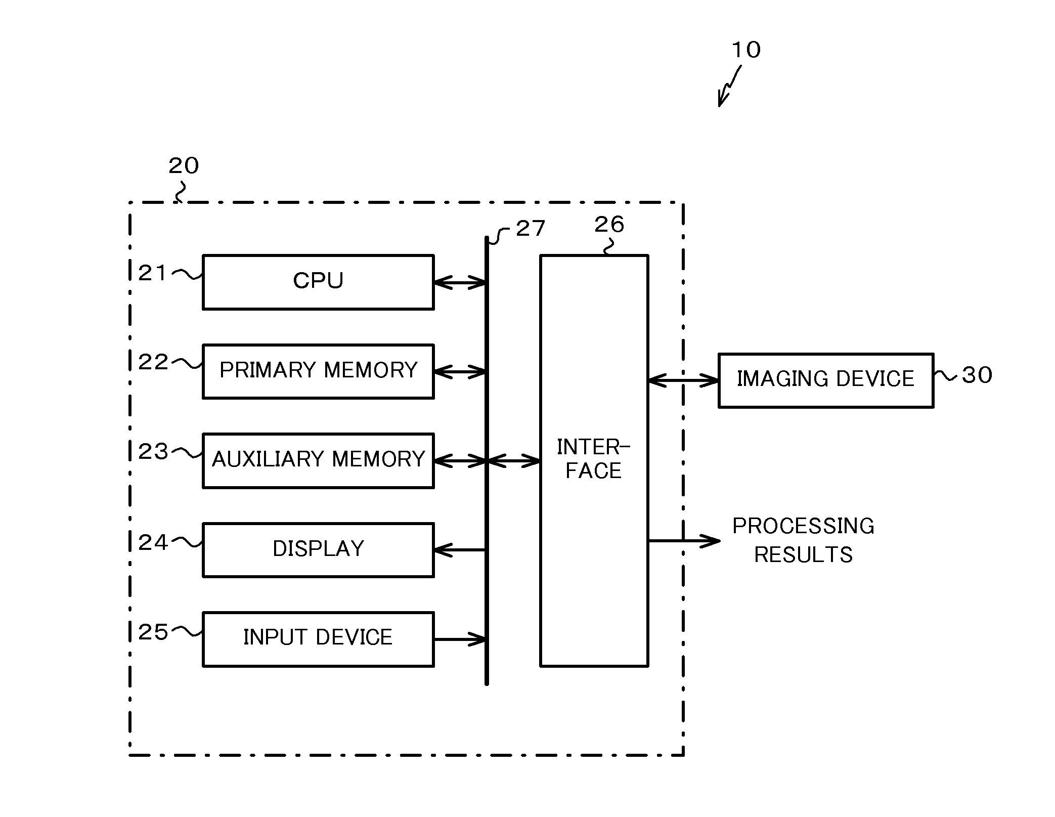
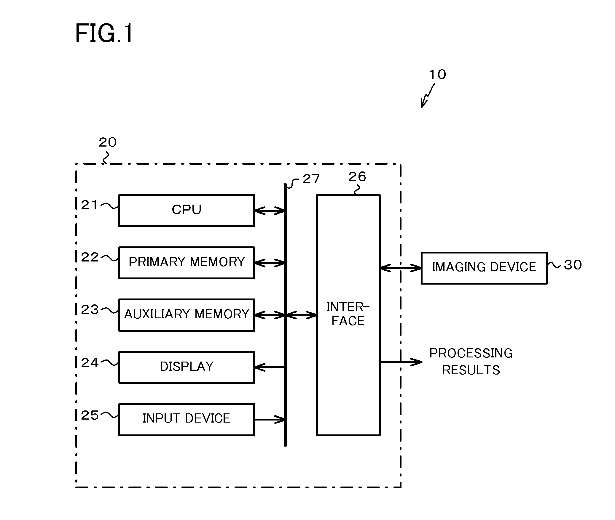
[0048]Hereinafter, the first embodiment of the present invention will be described with reference to the drawings. FIG. 1 is a block diagram illustrating a schematic configuration of an eyelid detection device 10 according to the present embodiment. The eyelid detection device 10 is a device that calculates a degree of opening of a driver's eyes, on the basis of an image depicting the driver's face. As illustrated in FIG. 1, the eyelid detection device 10 includes a calculating device 20 and an imaging device 30.

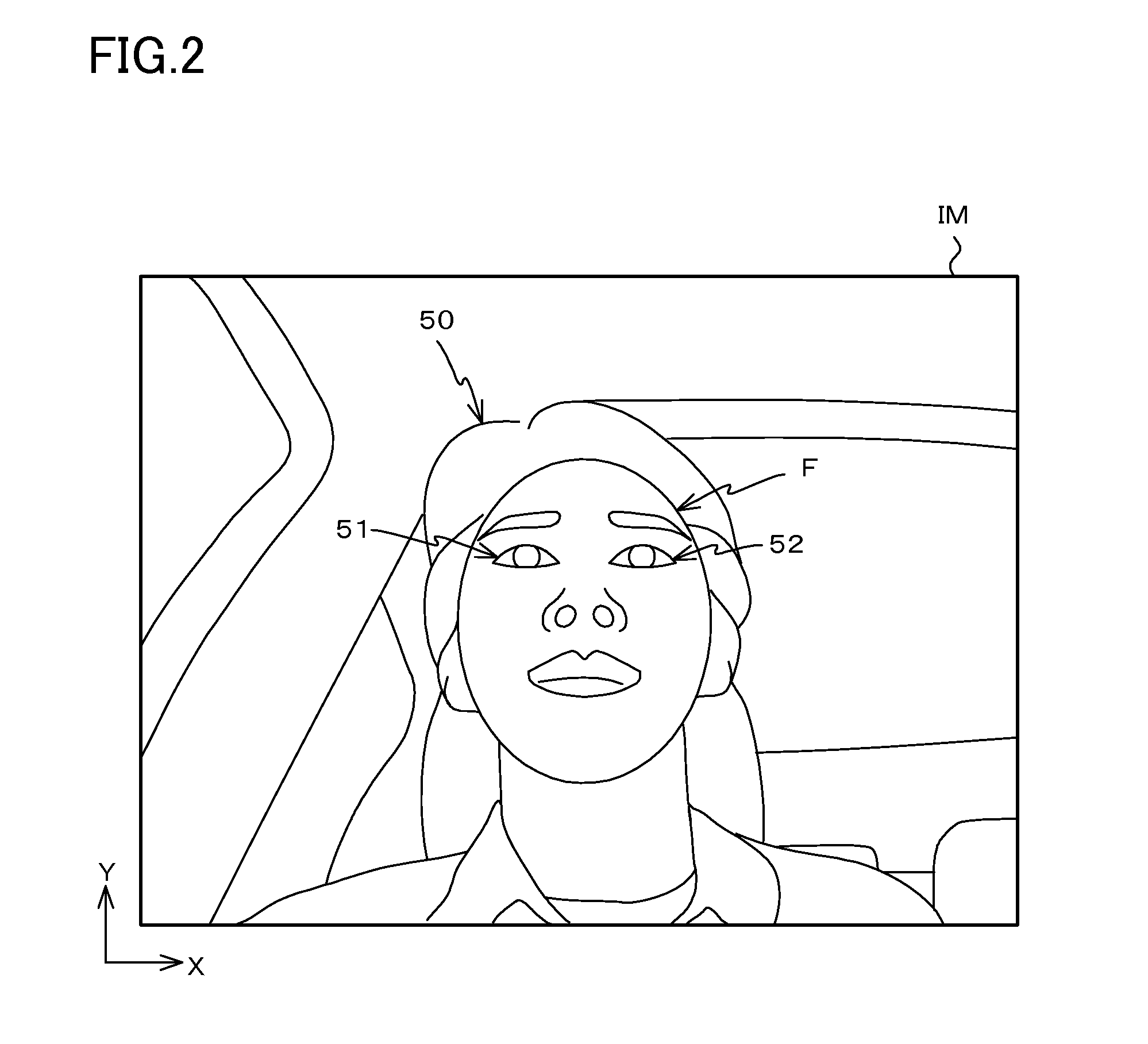
[0049]The imaging device 30 is a device that converts and outputs an image acquired by imaging a subject as an electrical signal. FIG. 2 illustrates an image IM captured by the imaging device 30. As the image IM demonstrates, the imaging device 30 is attached to the top of the steering column or the steering wheel, for example, with the installation angle and the angle of view adjusted such that the face of a driver 50 seated in the driver's seat of a vehicle is positioned i...

second embodiment

[0098]Next, the second embodiment of the present invention will be described with reference to the drawings. Note that like signs will be used for structural elements that are similar or identical to the first embodiment, and the description thereof will be simplified or omitted.

[0099]An eyelid detection device 10A according to the present embodiment differs from the eyelid detection device 10 according to the first embodiment in that the calculating device 20 is realized by hardware. As illustrated in FIG. 18, the eyelid detection device 10A includes memory 20a, a pixel extractor 20b, an upper eyelid position detector 20c, an eyelid search area setter 20d, an evaluation value calculator 20e, a second-order curve generator 20f, a reference position setter 20g, and a degree of opening calculator 20h.

[0100]The memory 20a successively stores information, including information regarding images output from the imaging device 30, processing results by the respective components 20b to 20h...


PUM


Abstract

A secondary curve, the ends of which coincide with the inner corner and the outer corner of the eye, is determined successively, and the total of the edge values of the pixels overlapping the secondary curve is calculated as an evaluation value. Next, a characteristic curve is generated on the basis of data made up of the calculated evaluation value and the Y-coordinate of the intersection between the secondary curve and a straight line passing through the center of a line segment whose ends coincide with the inner corner and the outer corner of the eye. Then, the reference positions for the upper eyelid and the lower eyelid of the eye are set on the basis of the result of an attempt to detect a pixel group occurring because of the red-eye effect in a search area defined on the basis of peaks in the characteristic curve.

Description

TECHNICAL FIELD[0001]The present invention relates to an eyelid detection device, an eyelid detection method, and a program, and more particularly, to an eyelid detection device that detects eyelids depicted in an image of the eyes, and to an eyelid detection method and program for detecting eyelids depicted in an image of the eyes.BACKGROUND ART[0002]Recently, traffic accident fatalities tend to be decreasing, but the number of incidents still remains at a high level. Although the causes of accidents are various, driving a vehicle while the driver is in a state of decreased alertness, such as being asleep at the wheel, is one factor that leads to accidents.[0003]Consequently, various technologies for precisely detecting decreases in a driver's alertness have been proposed (see Patent Literature 1, for example).CITATION LISTPatent Literature[0004]PLT 1: Unexamined Japanese Patent Application Kokai Publication No. 2004-192552.SUMMARY OF INVENTIONTechnical Problem[0005]The device disc...

Claims


Application Information

Patent Timeline
IPC IPC(8): G06K9/00
CPCG06K9/0061G06K9/00845G06V40/193G06V20/597
Inventor HIRAMAKI, TAKASHINAKABAYASHI, ATSUSHIUSAMI, MASAYUKINISHINA, TAMIKOIIDA, HIROAKI
Owner AISIN SEIKI KK
Why Eureka
Try Eureka