
Blow-molding machine for plastic containers

Inactive Publication Date: 2014-06-12
KRONES AG
View PDF8 Cites 3 Cited by
  • Summary
  • Abstract
  • Description
  • Claims
  • Application Information

AI Technical Summary

Benefits of technology

The present patent discloses a blow-molding machine that can open and close blow mold cavities quickly, and can simplify the drive for the machine's halves. The machine uses multi-carriers that can move simultaneously, saving energy and time. This machine can realize combined motion sequences for closing and opening several blow mold cavities with minimal energy input and without interruptions during the loading and removal processes. The technical effects of this patent are improved production efficiency and more economical production.

Problems solved by technology

Process time is consumed for the associated acceleration and deceleration ramps, i.e. for the duration of the acceleration and deceleration phases, and comparatively complex drive control is required for the blow mold halves.
EP 1 226 017 B1 proposes an improved blow-molding machine, but radially movable holding arms for the mold carriers are proposed for increasing capacity, the implementation and motion coordination of which is complex.

Method used


Image

  • Blow-molding machine for plastic containers
  • Blow-molding machine for plastic containers
  • Blow-molding machine for plastic containers

Examples


embodiment 1

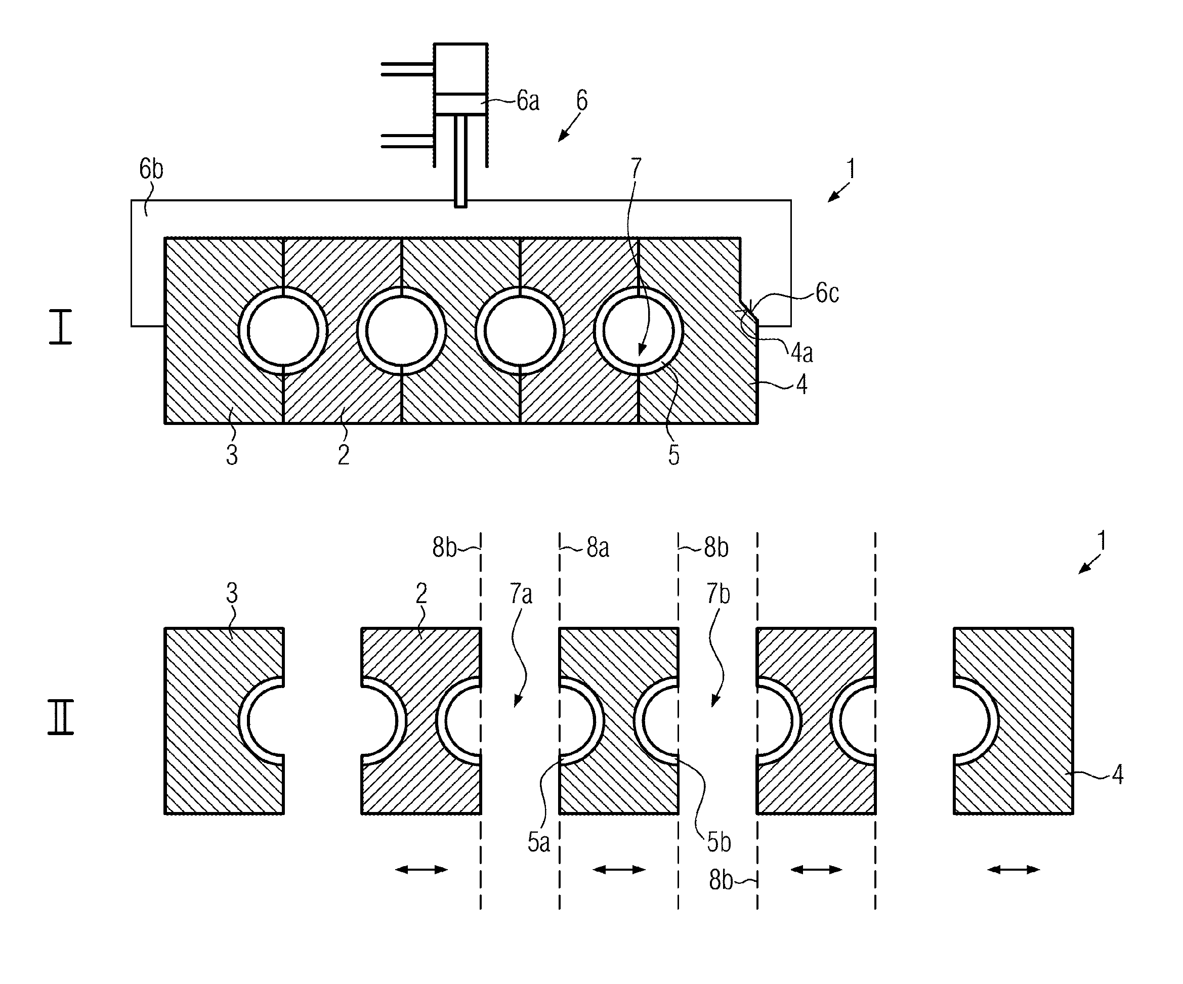
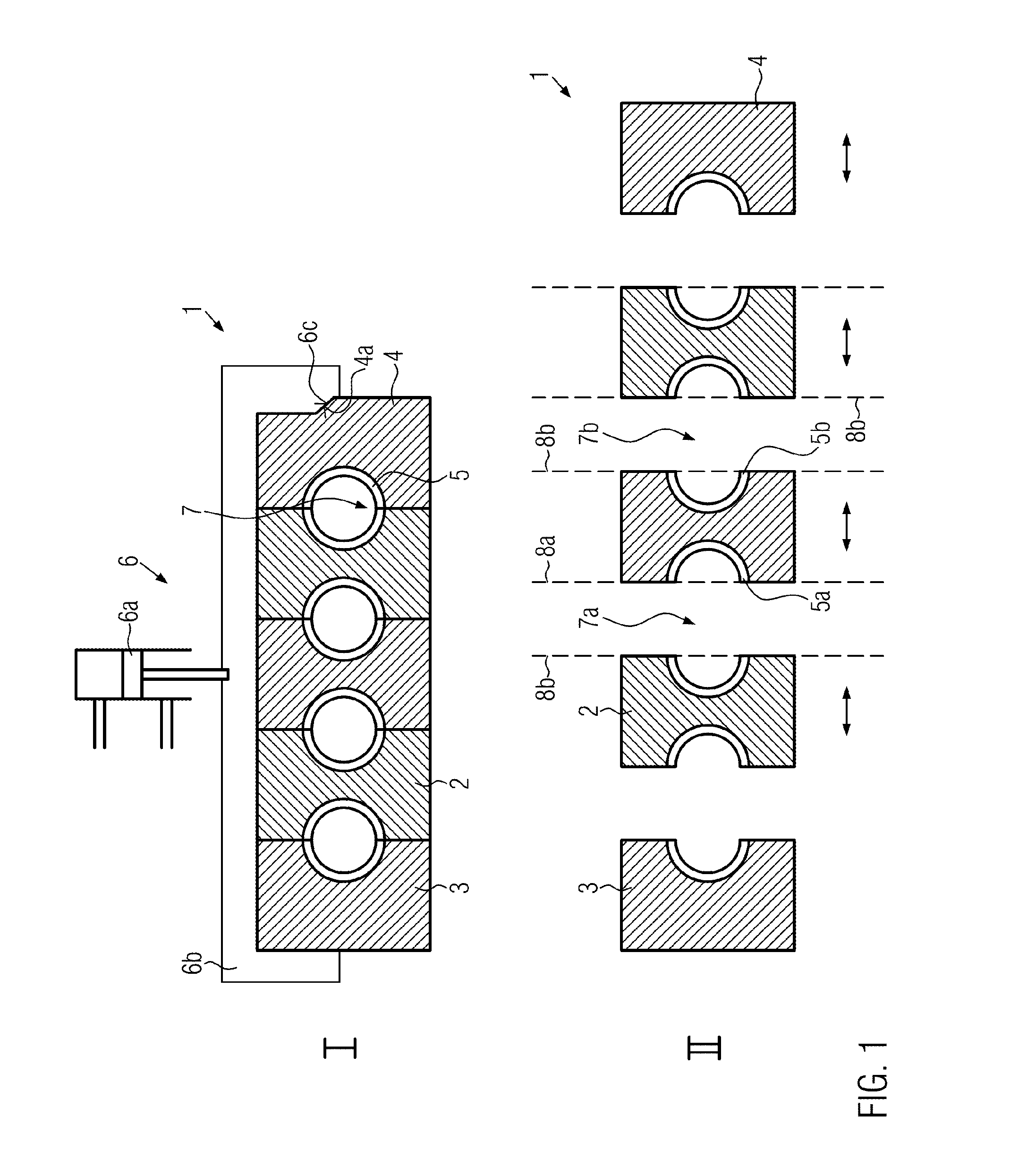
[0055]As FIG. 1 illustrates, a first, stationary embodiment 1 of the blow-molding machine according to the present disclosure comprises a plurality of non-rotary mold carriers 2 to 4 for carrying blow mold halves 5. There is furthermore a locking device 6 provided for locking the mold carriers 2 to 4 in a closed position I in which the blow mold halves 5 include blow mold cavities 7. As FIG. 1 further illustrates, the locking device 6 can comprise a drive unit 6a and a clamp 6b that presses the mold carriers 2 to 4 onto each other. The clamp 6b is formed such that the blow mold cavities 7 are sealed according to the blowing pressure. For this purpose, for example, wedge surfaces 4a, 6c or the like can be provided, for example, on mold carriers 3, 4 located at the edges and the bracket 6b.

[0056]FIG. 1 further shows the mold carriers 2 to 4 in a spread apart position II in which the blow mold cavities 7 are each open. It is further illustrated that, for example, the mold carrier 3 lo...

embodiment 181

[0087]FIG. 19 shows a nineteenth embodiment 181 of the blow-molding machine according to the present disclosure which differs from the eighteenth embodiment essentially in that two separate transport systems are provided for the preforms V and the fully blow-molded containers B. The preforms V and the container B can thereby be introduced into the blow mold cavities 7a to 7d or removed thereform in a particularly flexible manner.

[0088]FIG. 20 illustrates the position according to the present disclosure of the parting planes 8a, 8b using a common mold carrier 2. According thereto, the parting planes 8a, 8b of a double carrier indicated in FIG. 20 at the top are preferably disposed parallel and such that the associated blow mold halves face away from each other. With an imaginary superimposition of the parting planes 8a, 8b, each viewed in the direction of the arrow, an angle φ of 180° would thereby be formed between them or, expressed differently for double carriers, formed between t...


PUM

PropertyMeasurementUnit
Angleaaaaaaaaaa
Angleaaaaaaaaaa
Magnetic forceaaaaaaaaaa

Abstract

What is described is a blow-molding machine for plastic containers, comprising a plurality of platens for supporting blow mold halves, wherein at least two of the platens are in the form of movable multi-carriers for simultaneously supporting at least two blow mold halves which are assigned to different blow-molding cavities. Since the multi-carriers are driven in such a manner that at least one of the blow-molding cavities can be opened and at the same time at least one other of the blow-molding cavities can be closed by means of a continuous movement of the multi-carriers, acceleration and deceleration ramps can be reduced upon opening and closing and it is possible to gain process time for the blow molding.

Description

CROSS-REFERENCE TO RELATED APPLICATION[0001]The present application is the United States national phase of International Patent Application No. PCT / EP2012 / 058898, filed May 14, 2012, which application claims priority of German Application No. 102011079077.2, filed Jul. 13, 2011. The priority application, DE 102011079077.2, is incorporated herein by reference.FIELD OF THE DISCLOSURE[0002]The present disclosure relates generally to a blow-molding machine for plastic containers, and more specifically, to a blow-holding machine with a plurality of mold carries for blow mold halves, at least two of the mold carriers being movable multicarriers for simultaneously carrying at least two blow mold halves that are associated with different blow mold cavities.BACKGROUND[0003]Several blow-molding stations with blow molds are known to be provided on blow-molding machines for plastic containers, where the blow molds comprise at least two blow mold halves that are opened for inserting a preform an...

Claims


Application Information

Patent Timeline
IPC IPC(8): B29C49/56B29C49/42B29C49/12
CPCB29C49/56B29C49/4236B29C49/421B29C49/12B29C49/32B29C49/48B29C49/48185B29C49/42069
Inventor WINZINGER, FRANK
Owner KRONES AG
Learn More