Plasma-catalyzed fuel reformer system

a fuel reformer and plasma technology, applied in the direction of regenerative fuel cells, fuel cells, electrical equipment, etc., can solve the problems of fuel cell system loss, inability to reform, and heavy efficiency penalty of the fuel processor used to reform liquid fuel,

Inactive Publication Date: 2014-06-12
HARTVIGSEN JOSEPH J +3
View PDF1 Cites 6 Cited by
  • Summary
  • Abstract
  • Description
  • Claims
  • Application Information

AI Technical Summary

Benefits of technology

[0008]The invention has been developed in response to the present state of the art and, in particular, in response to the problems and needs in the art that have not yet been fully solved by currently available apparatus and methods. Accordingly, the invention has been developed to provide a plasma-catalyzed, thermally integrated reformer for fuel cell systems. The features and advantages of the invention will become more fully apparent from the following description and appended claims, or may be learned by practice of the invention as set forth hereinafter.

Problems solved by technology

However, where liquid fuels are used, a fuel processor used to reform liquid fuel exacts a heavy efficiency penalty on a fuel cell system.
Historically, the sulfur and aromatic content of transportation fuels has made them impossible to reform using the catalytic steam reforming process used with natural gas systems, due to problems with “poisoning” the catalyst and carbon buildup.
Although reformate produced by partial oxidation typically represents about 80% of the energy content of the fuel as measured by heating value, the use of any partial oxidation process coupled to any type of fuel cell results in a loss in the range of 30 to 40% of the electric power generation potential of the fuel.
Although steam reforming does not suffer from such an effect, no suitable catalysts are known for high-sulfur, hydrogen-lean transportation fuels.

Method used


Image

  • Plasma-catalyzed fuel reformer system
  • Plasma-catalyzed fuel reformer system
  • Plasma-catalyzed fuel reformer system

Examples


Embodiment Construction

[0027]It will be readily understood that the components of the present invention, as generally described and illustrated in the Figures herein, could be arranged and designed in a wide variety of different configurations. Thus, the following more detailed description of the embodiments of apparatus and methods in accordance with the present invention, as represented in the Figures, is not intended to limit the scope of the invention, as claimed, but is merely representative of certain examples of presently contemplated embodiments in accordance with the invention. The presently described embodiments will be best understood by reference to the drawings, wherein like parts are designated by like numerals throughout.

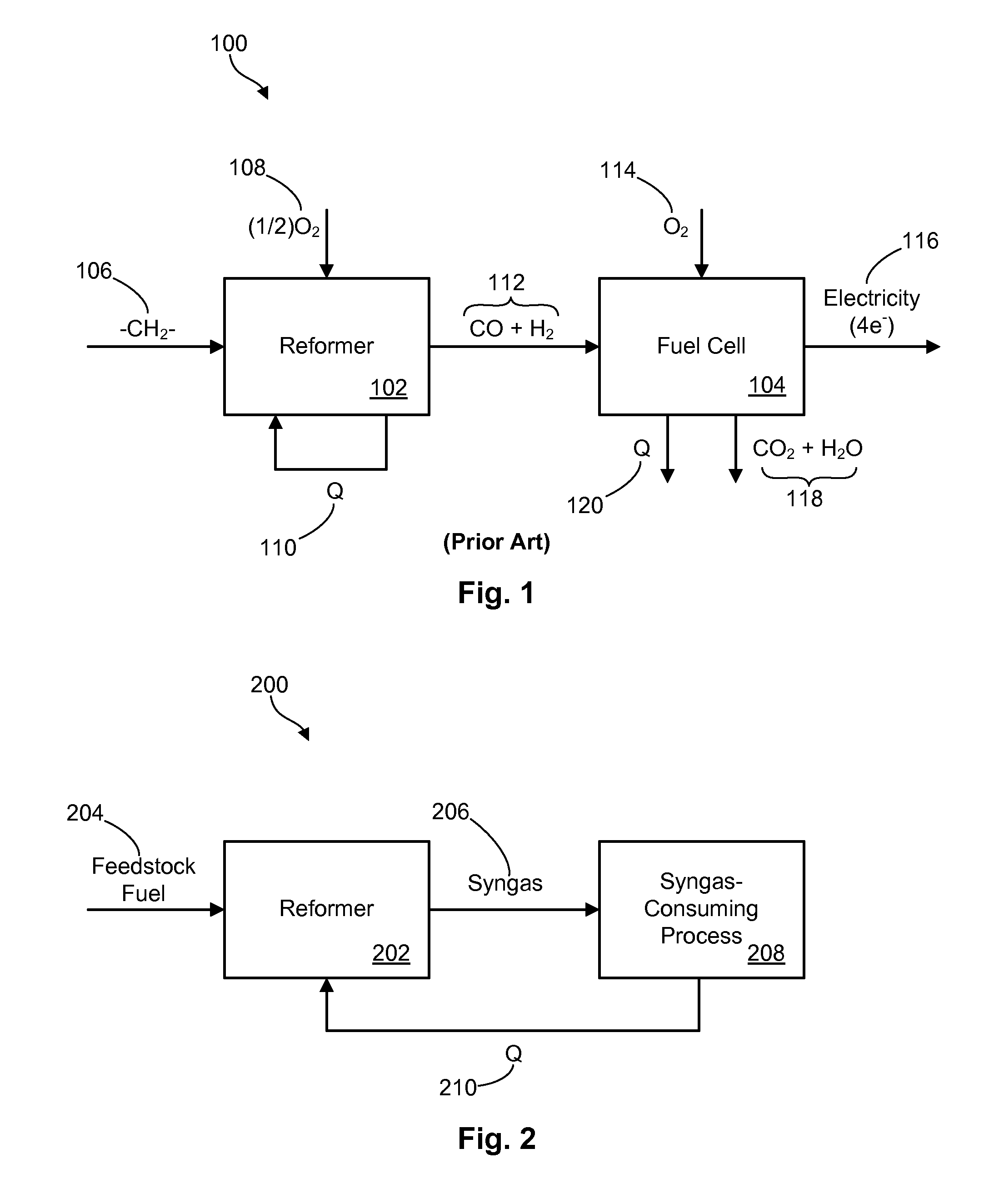
[0028]Referring to FIG. 1, in general, a prior art system 100 for producing electricity using a feedstock fuel 106 as an input may include a reformer 102, or fuel processor 102, and a fuel cell 104. The reformer 102 may receive and process a hydrocarbon feedstock fuel 106 t...


PUM

PropertyMeasurementUnit
temperaturesaaaaaaaaaa
thermally conductiveaaaaaaaaaa
surface areaaaaaaaaaaa

Abstract

A thermally integrated system for producing electricity from a feedstock fuel is disclosed. The system utilizes a reformer that includes a plasma zone to receive a pre-heated mixture of reactants and ionize the reactants by applying an electrical potential thereto. A first thermally conductive surface surrounds the plasma zone and is configured to transfer heat from an external heat source into the plasma zone. The reformer further includes a reaction zone to chemically transform the ionized reactants into synthesis gas comprising hydrogen and carbon monoxide. A second thermally conductive surface surrounds the reaction zone and is configured to transfer heat from the external heat source into the reaction zone. The first thermally conductive surface and second thermally conductive surface are both directly exposed to the external heat source. A corresponding method and apparatus are also disclosed herein.

Description

RELATED APPLICATIONS[0001]This patent application is a divisional application of and claims priority to U.S. patent application Ser. No. 12 / 537,953, filed Aug. 7, 2009, which claims priority to U.S. Provisional Patent Application No. 61 / 087,549, filed Aug. 8, 2008, and which is a continuation-in-part of U.S. patent application Ser. No. 11 / 745,942, filed May 8, 2007, which claims priority to U.S. Provisional Patent Application No. 60 / 798,863, filed May 8, 2006. These applications are incorporated by reference.GOVERNMENT RIGHTS[0002]At least part of the technology disclosed in this patent application may have been funded by the United States Government under the following contracts: Department of Energy DE-FG-02-07ER84663, Department of Defense (Army) W56-HZV-07-C-0577 and Department of Defense (Navy) N00014-07-M-0450. The United States Government may have certain rights in the invention.FIELD OF THE INVENTION[0003]The present invention relates to liquid fuel reformation and more part...

Claims


Application Information

Patent Timeline
Patent Type & Authority Applications(United States)
IPC IPC(8): H01M8/06
CPCH01M8/04022H01M8/04708H01M8/0618Y02E60/50
Inventor HARTVIGSEN, JOSEPH J.ELANGOVAN, S.CZERNICHOWSKI, PIOTRHOLLIST, MICHELE
Owner HARTVIGSEN JOSEPH J
Why Eureka
Try Eureka