Motor programming tool with handle-mounted PCB

a technology for motors and controllers, applied in the direction of coupling contact members, coupling device connections, testing/measuring connectors, etc., can solve the problems of requiring significant insertion and separation force, time-consuming and labor-intensive established connection systems, and requiring plugging and unplugging of mating terminals, etc., to achieve fast and consistent operation, long useful tool life, and convenient use

Active Publication Date: 2014-06-12
NIDEC MOTOR CORP
View PDF3 Cites 7 Cited by
  • Summary
  • Abstract
  • Description
  • Claims
  • Application Information

AI Technical Summary

Benefits of technology

[0008]The present invention provides a motor programming tool for associating with a connection block of a motor and sending signals to a programmable controller of the m

Problems solved by technology

While prior art motor programming tools have been satisfactory in some respects, the required plugging and unplugging of the mating terminals has also presented drawbacks.
These established connection systems are time consuming and require significant insertion and separation force to connect and then remove the mating terminals and sockets.
As is generally known in the art, the mating terminals and sockets provided between the motor connection block and existing programming tools are not particularly suited for multiple plugging and unplugging operations during the life span of the components.
Such repe

Method used


Image

  • Motor programming tool with handle-mounted PCB
  • Motor programming tool with handle-mounted PCB
  • Motor programming tool with handle-mounted PCB

Examples


Embodiment Construction

[0038]The present invention is susceptible of embodiment in many different forms. While the drawings illustrate, and the specification describes, certain preferred embodiments of the invention, it is to be understood that such disclosure is by way of example only. There is no intent to limit the principles of the present invention to the particular disclosed embodiments.

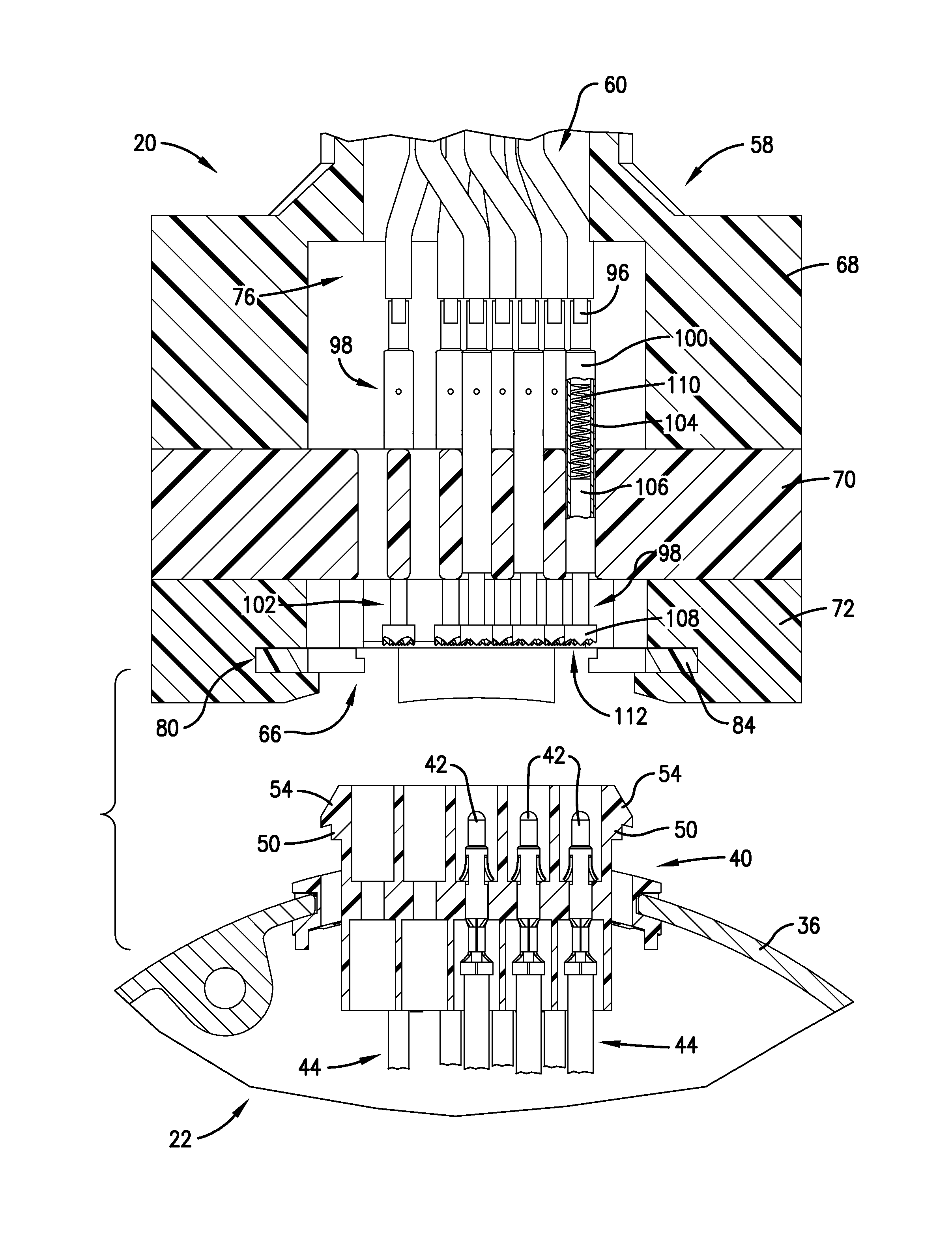
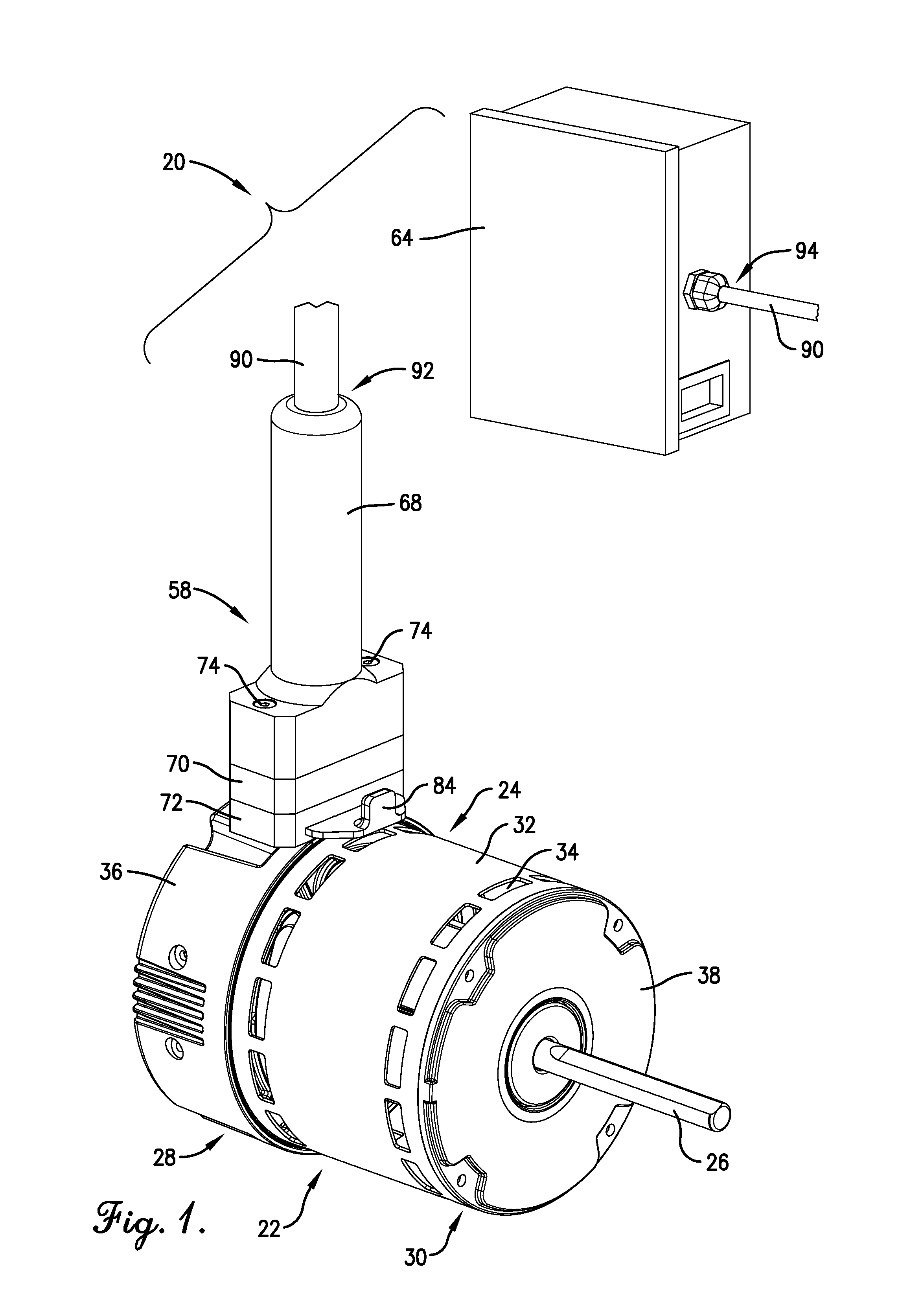
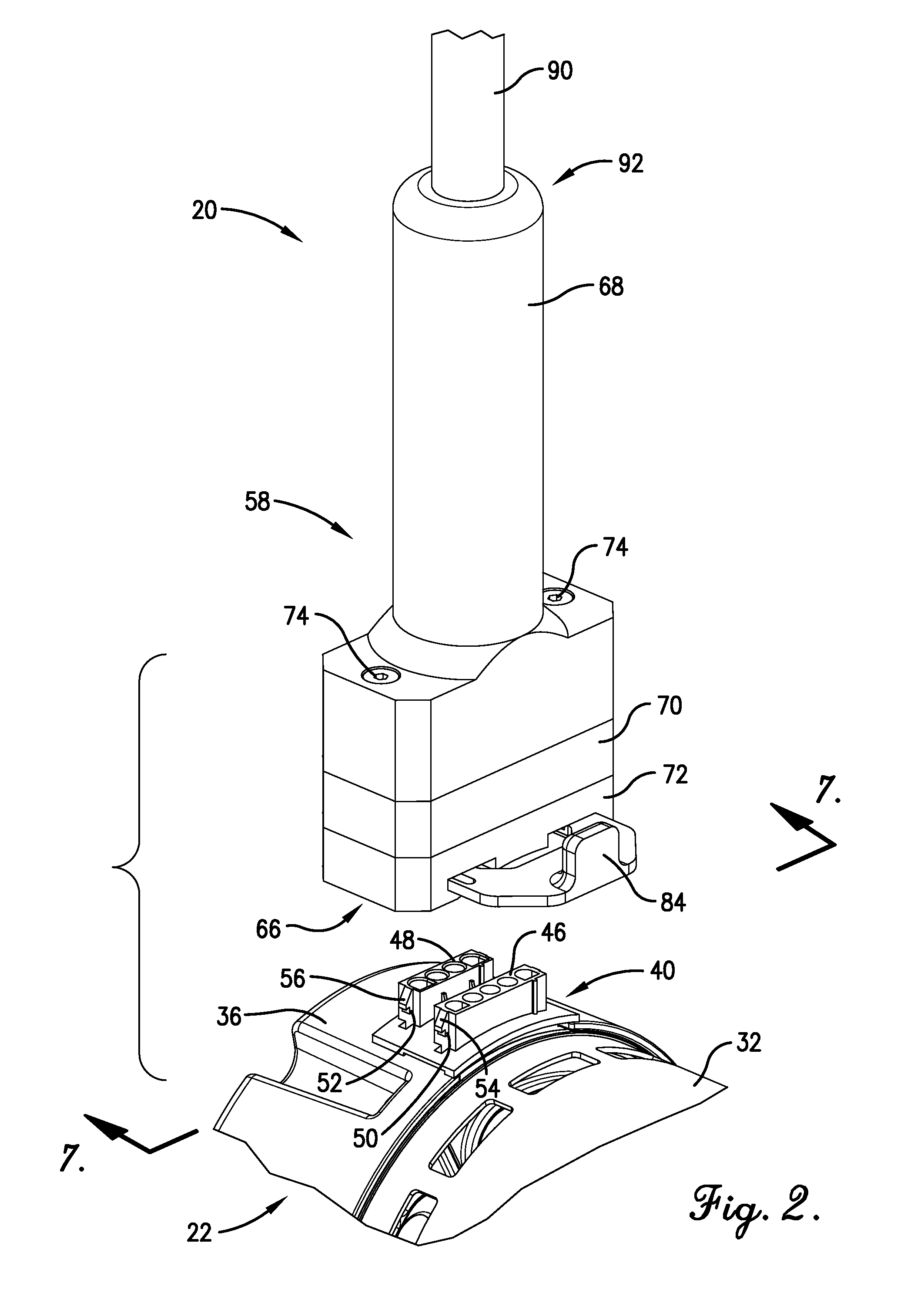
[0039]With initial reference to FIGS. 1-8, a motor programming tool 20 constructed in accordance with an embodiment of the present invention is depicted for temporarily associating with an electric motor 22.

[0040]As is generally customary, the motor 22 broadly includes a rotor assembly (not shown), rotatable about an axis, and a stator assembly (not shown). The rotor assembly and the stator assembly are both contained within an internal motor chamber that is defined by a motor case 24. As shown in FIG. 1, the rotor assembly includes an axially disposed shaft 26 that projects outwardly from one end of the motor case 2...


PUM


Abstract

A motor programming tool is disclosed for associating with a connection block of a motor and sending signals to a programmable controller of the motor, where the connection block includes a plurality of terminals coupled to the controller. The programming tool includes a tool body with an interface generally corresponding with the connection block of the motor, wiring operable to carry the signals, and a plurality of terminal connecting assemblies to associate with the motor terminals. The programming tool includes circuitry disposed in the tool body. The circuitry is electrically connected to the wiring and includes a power transmission portion and a data transmission portion.

Description

BACKGROUND OF THE INVENTION[0001]1. Field of the Invention[0002]The present invention relates generally to a tool for programming electric motor controllers. More specifically, the present invention concerns a motor programming tool for temporarily associating with an electrical connection block of a motor to send electrical signals to a programmable controller of the motor.[0003]2. Discussion of the Prior Art[0004]Those of ordinary skill in the art will appreciate that electric motors typically include a controller that governs parameters of how the motor operates (e.g., speed). The motor controller may be programmable, which can allow a motor with a given physical construction to be programmed to operate in a certain desirable manner, as may be particularly advantageous when the motor is coupled with a driven machine (e.g., a blower or a compressor). In this way, a number of motors, which otherwise may be physically alike, can each operate differently based on the settings of the ...

Claims


Application Information

Patent Timeline
IPC IPC(8): H01R13/15
CPCH01R13/2421H01R13/6275H01R13/6658H01R2201/20
Inventor GEILER, CHARLES L.PLOOF, JR., ROBERT J.MODI, CHETAN O.RASSOOLKHANI, PAYMAN
Owner NIDEC MOTOR CORP
Why Eureka
Try Eureka