Transmitter To Receiver Communication Link In A Wireless Power System

a communication link and transmitter technology, applied in the field of wireless power systems, can solve the problems that the transmitter cannot query and obtain any information from the receiver

Inactive Publication Date: 2014-06-12
WIPQTUS
View PDF17 Cites 31 Cited by
  • Summary
  • Abstract
  • Description
  • Claims
  • Application Information

AI Technical Summary

Benefits of technology

[0006]A method and system for establishing a communication link in a wireless power system is provided. The wireless power system comprises a wireless power transmitter and a wireless power receiver. A flux modulator is operably disposed in the wireless power transmitter to send messages to the wireless power receiver. Furthermore, a flux demodulator is operably disposed in the wireless power receiver to recover the messages sent by the flux modulator. The flux modulator is configured to dynamically change the wireless power transmitter's input impedance through a multitude of techniques, for example, an inductance change, a capacitance change, a resistance change, etc., and any combination thereof to change the current in the transmitter coil and hence modulate the transmitted magnetic flux field intensity. The modulated magnetic field of the transmitter coil induces a modulated secondary voltage on a receiver coil. The induction of the modulated secondary voltage on the receiver coil due to the modulated magnetic field on the transmitter coil establishes the communication link between the wireless power transmitter and the wireless power receiver in the wireless power system. The flux demodulator is configured to receive and demodulate the secondary voltage induced on the receiver coil for obtaining information from the wireless power transmitter.

Problems solved by technology

As a result, the transmitter cannot query and obtain any information from the receiver.

Method used


Image

  • Transmitter To Receiver Communication Link In A Wireless Power System
  • Transmitter To Receiver Communication Link In A Wireless Power System
  • Transmitter To Receiver Communication Link In A Wireless Power System

Examples


first embodiment

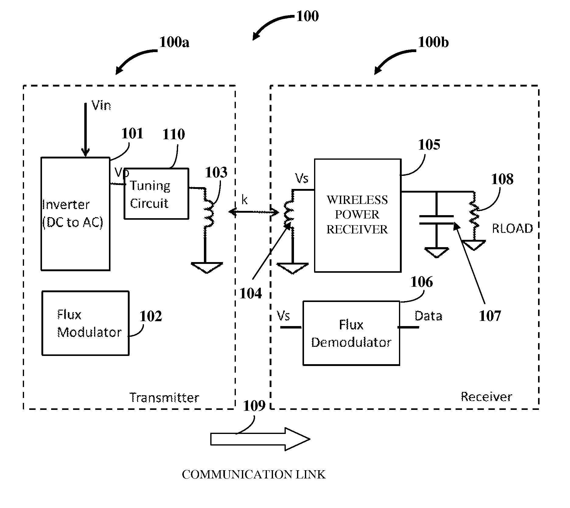
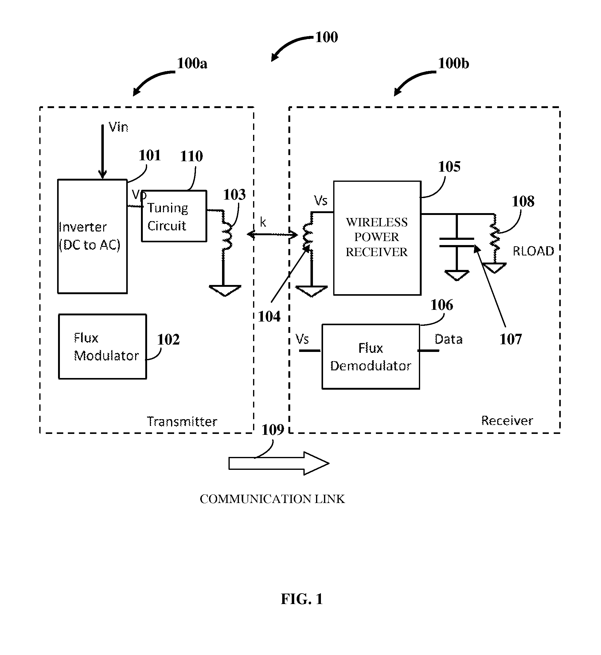
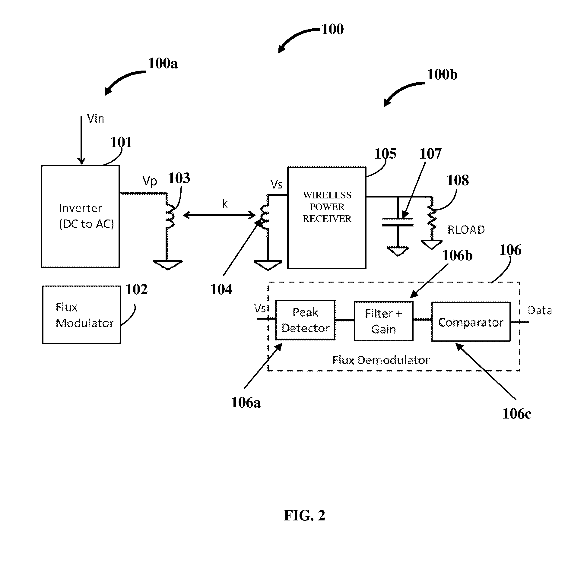
[0022]FIG. 2 exemplarily illustrates the system 100 for establishing a communication link 109 between a wireless power transmitter 100a and a wireless power receiver 100b of a wireless power system, where the flux demodulator 106 in the wireless power receiver 100b is configured as an analog signal processing chain. The analog signal processing chain decodes the information obtained from the wireless power transmitter 100a via the established communication link 109 exemplarily illustrated in FIG. 1. The analog signal processing chain in the flux demodulator 106 processes the secondary voltage to obtain an analog representation of a message transmitted by the flux modulator 102. The flux demodulator 106 configured as the analog signal processing chain comprises a peak detector 106a, a filter gain block 106b, and a comparator 106c. The voltage induced across the receiver coil 104, Vs, is fed as an input to the peak detector 106a. The peak detector 106a determines the peak of the AC va...

second embodiment

[0023]FIG. 3 exemplarily illustrates the system 100 for establishing a communication link 109 between a wireless power transmitter 100a and a wireless power receiver 100b of a wireless power system, where the flux demodulator 106 is configured as a digital signal processing block 106d. The digital signal processing block 106d converts the secondary voltage, Vs, induced across the receiver coil 104 that is directly fed as input to the digital signal processing block 106d, into digital data. That is, the digital signal processing block 106d decodes the information obtained from the wireless power transmitter 100a via the established communication link 109 exemplarily illustrated in FIG. 1. The digital signal processing block 106d processes the secondary voltage to obtain a digital representation of the message transmitted by the flux modulator 102. The digital signal processing block 106d recovers the message sent by the wireless power transmitter 100a.

[0024]FIG. 4A exemplarily illus...

third embodiment

[0026]FIG. 5A exemplarily illustrates the flux modulator 102 in the wireless power transmitter 100a of the wireless power system. The tuning circuit 110 is in series with the transmitter coil 103. The tuning circuit 110 comprises a primary capacitor and a communication modulation capacitor that is connected in parallel with the primary capacitor. The primary capacitor is represented as CTX and the communication modulation capacitor is represented as CMOD. The flux modulator control module 102a in the flux modulator 102 is configured to change the wireless power transmitter's 100a input impedance (as seen by the power source) by selecting the primary capacitor or both the primary capacitor and the communication modulation capacitor. If switch S1 is open, the impedance of the tuning circuit 110 is (−j / W*CTX). If switch S1 is closed, the impedance of the tuning circuit 110 changes to (−j / W*(CTX+CMOD)). This change in impedance of the tuning circuit 110 changes the impedance of the wire...


PUM


Abstract

A method and system for establishing a communication link in a wireless power system from a wireless power transmitter (WPT) to a wireless power receiver (WPR) is provided. A flux modulator is operably disposed in the WPT for dynamically changing the WPT's impedance so as to modulate a magnetic field produced on the transmitter coil when a primary voltage applied to the WPT. A flux demodulator is operably disposed in the WPR for receiving and demodulating a secondary voltage induced on a receiver coil due to the modulated magnetic field on the transmitter coil. The induction of the secondary voltage on the receiver coil due to the modulated magnetic field on the transmitter coil establishes the communication link from the WPT to the WPR. The flux demodulator is configured as an analog signal processing chain or a digital signal processing block for decoding information obtained from the WPT.

Description

CROSS REFERENCE TO RELATED APPLICATIONS[0001]This application claims the benefit of provisional patent application No. 61 / 673,736 titled “Transmitter To Receiver Communication Link In A Wireless Charging System”, filed in the United States Patent and Trademark Office on Jul. 20, 2012.[0002]The specification of the above referenced patent application is incorporated herein by reference in its entirety.BACKGROUND[0003]A wireless power system typically comprises a wireless power transmitter and a wireless power receiver. The wireless power transmitter transmits power wirelessly using a transmitter coil. Through the transmitter coil, the wireless power transmitter creates an electromagnetic field in a coupling region for providing energy transfer to the wireless power receiver. The wireless power receiver comprises a receiver coil that picks up the electromagnetic field. A voltage is induced in a receiver coil due to the electromagnetic field emanating from the transmitter coil. In the ...

Claims


Application Information

Patent Timeline
Patent Type & Authority Applications(United States)
IPC IPC(8): H04B10/114
CPCH04B5/0031H04B5/0037H04B5/0081H02J50/80H02J50/10H02J50/12
Inventor SANKAR, GANAPATHYSINGH, MANJIT
Owner WIPQTUS
Why Eureka
Try Eureka