
Method of acoustic surveying

a technology of acoustic surveying and measurement method, applied in the field of acoustic surveying, can solve the problems of limited flow measurement at a limited number of discrete locations, and the current technology is limited to flow measurement at a limited number of discrete locations, and skilled people could employ

Active Publication Date: 2014-06-12
SILIXA
View PDF1 Cites 32 Cited by
  • Summary
  • Abstract
  • Description
  • Claims
  • Application Information

AI Technical Summary

Benefits of technology

The patent text explains how analyzing variations in a certain function can help determine the location of defects or changes. By monitoring these variations over time, we can better track and prevent damage or malfunctions. This technique combines the benefits of position-based analysis and time-based analysis to provide a better understanding of where and when defects occur and how they develop.

Problems solved by technology

However, current technologies are limited to flow measurements at a limited number of discrete locations, for example by permanent installation of optical flow meters at a number of spaced locations along a length of production tubing.
However, using such a flow metering system again only allows measurements to be made at discrete points—although by measuring the speed of sound in the tubing the contents of the tubing can be determined, albeit only at those discrete points.
Such a measurement requires an intervention, and so is generally undesirable.
However, it is not obvious how the skilled person could employ the iDAS technology to produce meaningful survey data or useful distributed flow data.

Method used


Image

  • Method of acoustic surveying
  • Method of acoustic surveying
  • Method of acoustic surveying

Examples


Embodiment Construction

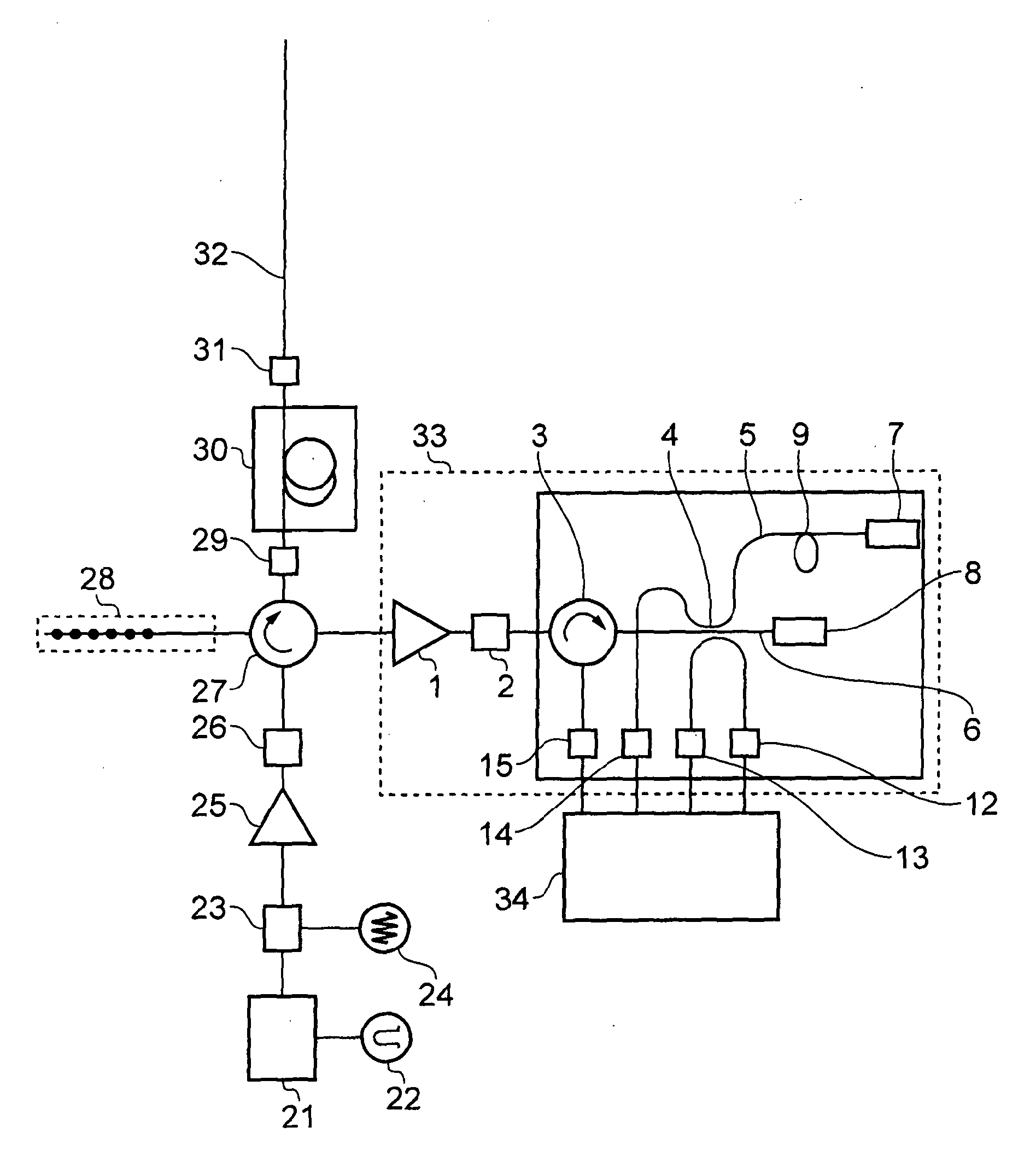
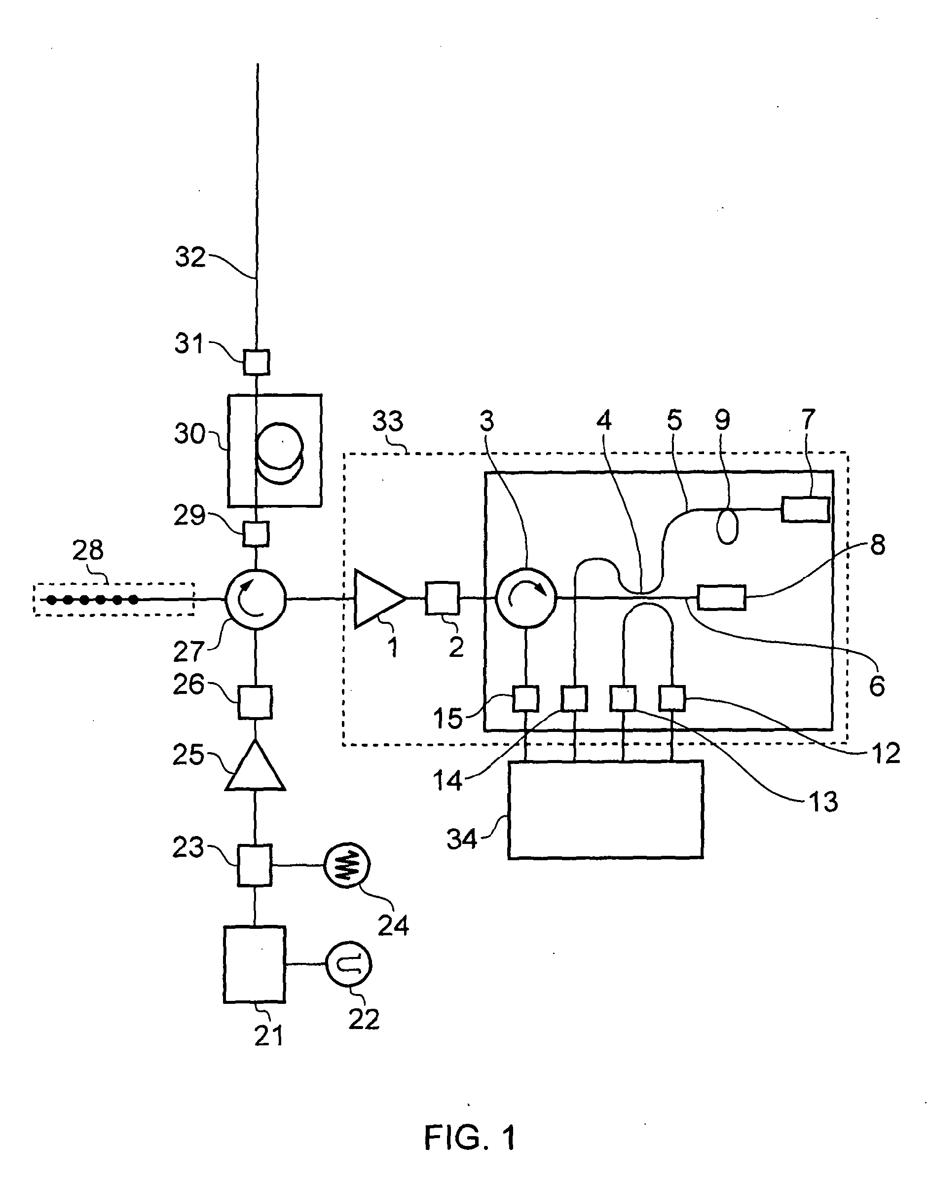
[0043]In a particular embodiment of the invention, described here in order to provide an example of a preferred implementation of the present invention, a plurality of acoustic sensors is provided in a distributed optical fibre sensor which comprises a length of optical fibre—located in a location or environment to be monitored as illustrated in FIG. 1. Examples of such distributed sensor arrangements are described in Silixa Limited's international patent application publication numbers WO2010 / 136809A2 and WO2010 / 136810A2 and in further detail below. Using such interferometers as an optical sensor, it is possible to make measurements of acoustic phase, frequency and amplitude from an optical sensor with high sensitivity, high speed of measurement and a large dynamic range.

[0044]With reference to FIG. 1, light emitted by a laser (21) is modulated by a pulse signal (22). An optical amplifier (25) is used to boost the pulsed laser light, and this is followed by a band-pass filter (26) ...


PUM


Abstract

The invention relates to the use of distributed optical fibre sensors for distributed acoustic sensing, and in particular, modal analysis of distributed acoustic data obtained in-well to monitoring well integrity. By determining one or more acoustic modes corresponding to distributed speed of sound measurements within the wellbore, and analysing variations in the distributed speed of sound measurement it is possible to derive information relating to a formation and / or fluid in the wellbore.

Description

[0001]The present invention relates to distributed optical fibre sensors for distributed acoustic sensing, methods of use in acoustic surveying and applications thereof. In particular, modal analysis of distributed acoustic data obtained in-well provides a means for monitoring well integrity.BACKGROUND TO THE INVENTION[0002]Flow metering is a key measurement when attempting to optimise production from a well. However, current technologies are limited to flow measurements at a limited number of discrete locations, for example by permanent installation of optical flow meters at a number of spaced locations along a length of production tubing.[0003]Well integrity is also a key concern. However, using such a flow metering system again only allows measurements to be made at discrete points—although by measuring the speed of sound in the tubing the contents of the tubing can be determined, albeit only at those discrete points.[0004]Noise logging can also be employed to determine in-well f...

Claims


Application Information

Patent Timeline
Patent Type & Authority Applications(United States)
IPC IPC(8): E21B47/00
CPCG01V1/226G01H9/004E21B47/107E21B47/135F17D3/00F17D5/00E21B47/06E21B49/08G01V1/40E21B47/005
Inventor FINFER, DANIELJOHANNESSEN, KJETIL
Owner SILIXA
Learn More