Method of connecting electric cable to connector terminal and compression-molding die

a technology of compression molding and electric cables, which is applied in the direction of metal working apparatus, dustproof/splashproof/drip-proof/waterproof/flameproof connection, etc., can solve the problems of difficult automation and increase in equipment costs, and achieve the effect of reducing equipment costs, simplifying work, and performing easily

Active Publication Date: 2014-06-19
YAZAKI CORP
View PDF11 Cites 9 Cited by
  • Summary
  • Abstract
  • Description
  • Claims
  • Application Information

AI Technical Summary

Benefits of technology

[0007]The present invention is made in view of the situation described above. An object of the present invention is to provide a method of connecting an electric cable to a connector terminal and a compression-molding die by which equipment costs are suppressed and automation is easily performed and thereby productivity can be improved.
[0016]In the method of connecting the electric cable to the connector terminal of the configurations (1) to (3) described above, compression of the electric cable and molding of the resin mold are performed in the same process so that complicated work of moving the connector terminal where the electric cable is compressed can be omitted and simplification of the work can be achieved. In addition, the equipment costs can be decreased and automation can be easily performed and thereby the improvement of productivity can be achieved compared to the case where compression of the electric cable and molding of the resin mold are performed separately in the compression machine and the molding machine, respectively.
[0024]In the compression-molding die of the configuration (4) to (6) described above, compression of the electric cable and molding of the resin mold can be performed easily in the same process and the complicated work of moving the connector terminal, where the electric cable is compressed, can be omitted and thereby simplification of the work can be achieved. In addition, the equipment costs can be reduced and automation thereof can be easily performed and thereby an improvement in productivity can be achieved compared to a case where compression of the electric cable and molding of the resin mold are performed separately in a compression machine and a molding machine, respectively.
[0025]According to the present invention, there are provided a method of connecting an electric cable to a connector terminal and a compression-molding die by which equipment costs are suppressed and automation is easily performed and thereby productivity can be improved.

Problems solved by technology

Thus, it is necessary to provide separate pieces of equipment which perform a compression process and a molding process, respectively, and equipment costs increase.
In addition, as described above, in a case where the compression process and the molding process are performed by separate facilities, improvement of productivity through automation is difficult.

Method used


Image

  • Method of connecting electric cable to connector terminal and compression-molding die
  • Method of connecting electric cable to connector terminal and compression-molding die
  • Method of connecting electric cable to connector terminal and compression-molding die

Examples


Embodiment Construction

[0032]Hereinafter, an embodiment of the present invention is described with reference to the drawings.

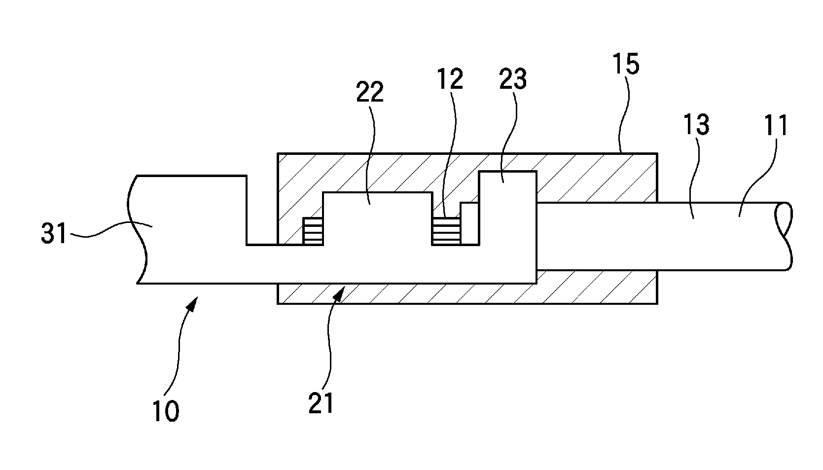
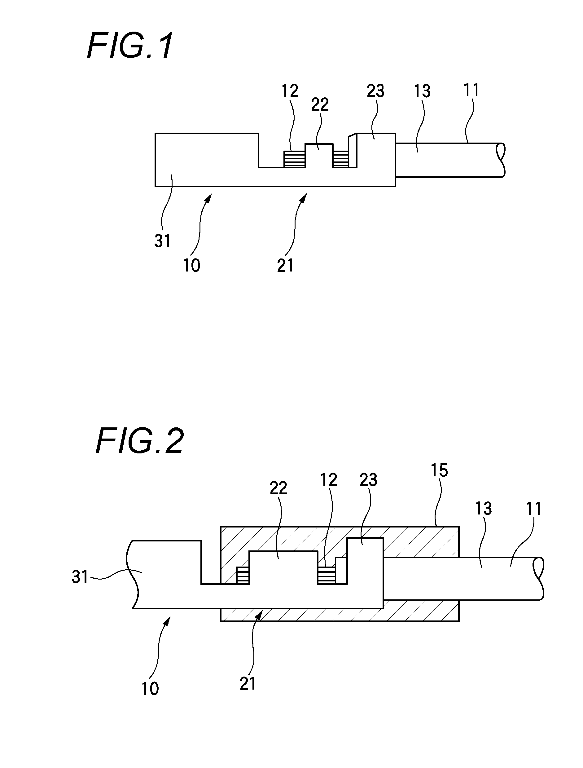
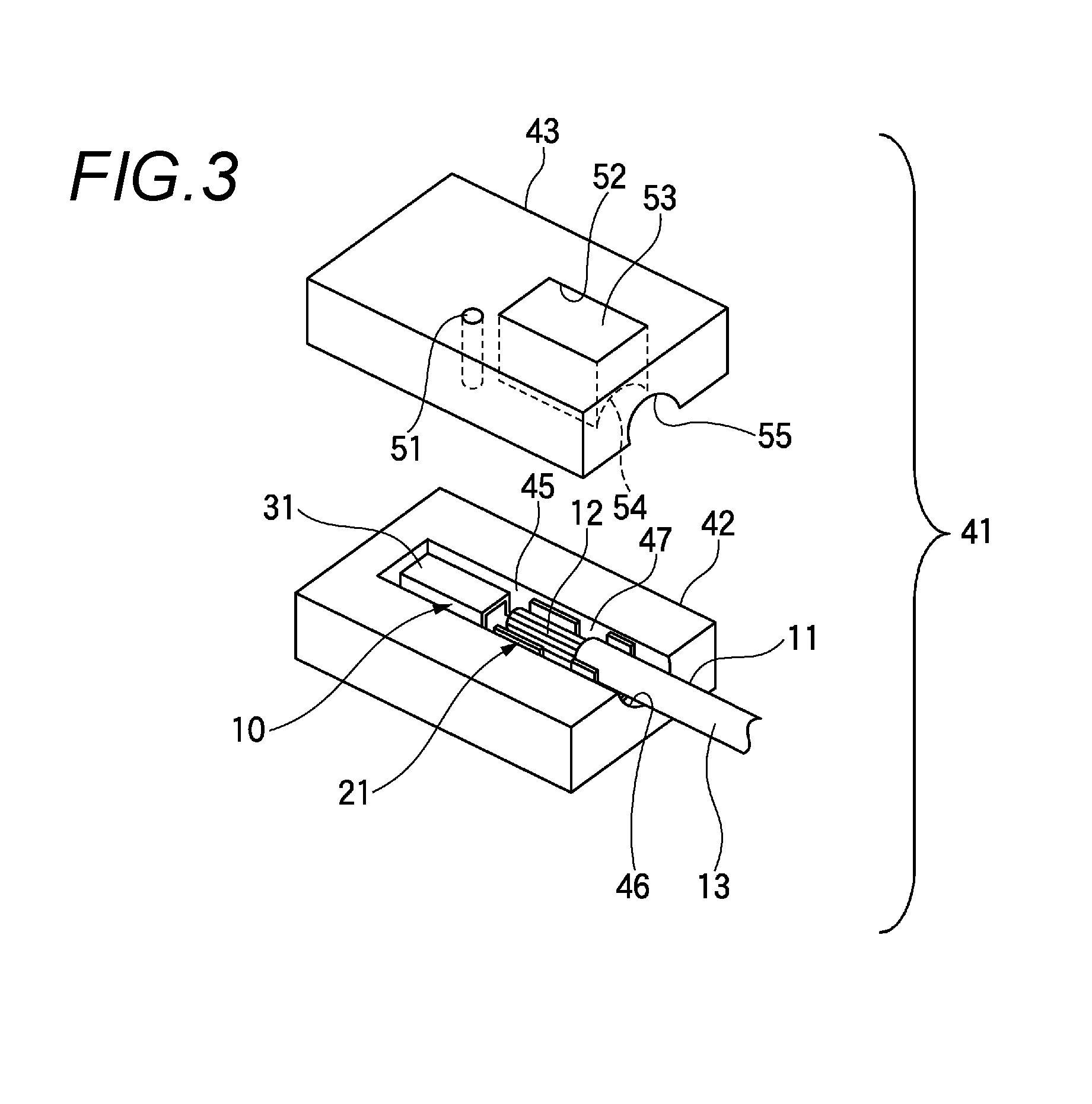
[0033]FIG. 1 is a side view of a connector terminal, FIG. 2 is a side view of the connector terminal where a resin mold is provided, FIG. 3 is a perspective view of a compression-molding die according to the embodiment, and FIGS. 4A to 4E are explanatory diagrams for explaining connecting processes of an electric cable to a connector terminal using a compression-molding die.

[0034]As shown in FIGS. 1 and 2, a connector terminal 10 in which an electric cable 11 is connected by a connection method according to the embodiment, is formed of a conductive metal material such as copper or copper alloy with, for example, press processing. The connector terminal 10 includes a barrel portion 21 and a tab terminal portion 31.

[0035]The electric cable 11, in which the connector terminal 10 is connected, has, for example, a core wire (a conductor) 12 formed of aluminum or aluminum alloy, and an ou...


PUM

PropertyMeasurementUnit
waterproof propertyaaaaaaaaaa
conductiveaaaaaaaaaa
corrosion resistanceaaaaaaaaaa

Abstract

A method of connecting an electric cable to a connector terminal includes arranging a connector terminal in a lower die so that an end portion of the electric cable in which a core wire is exposed from an outer cover is arranged in a barrel portion of the connector terminal, pressing a crimper to the barrel portion to crimp the barrel portion, overlapping the lower die with an upper die to form an injection space around the barrel portion and the end portion of the electric cable, and injecting a resin in an injection space, thereby forming a resin mold that covers and waterproofs the barrel portion and the end portion of the electric cable.

Description

CROSS REFERENCE TO RELATED APPLICATIONS[0001]This application is a continuation of PCT application No. PCT / JP2012 / 071372, which was filed on Aug. 17, 2012 based on Japanese Patent Application (No. 2011-182992) filed on Aug. 24, 2011, the contents of which are incorporated herein by reference.BACKGROUND OF THE INVENTION[0002]1. Field of the Invention[0003]The present invention relates to a method of connecting an electric cable to a connector terminal and a compression-molding die.[0004]2. Description of the Related Art[0005]In the related art, a technique is known in which, in order to maintain a waterproof property in a connector terminal to be connected to an end portion of a cable, a mold portion of a molding cavity is provided inside a molding metallic die configured of upper and lower dies, which accommodates and sets the terminal connection portion that compresses a terminal fitting to a conductor of a front end portion of a coated electric cable, and a mold resin in a molten ...

Claims


Application Information

Patent Timeline
Patent Type & Authority Applications(United States)
IPC IPC(8): H01R43/24
CPCH01R4/185H01R4/70H01R43/005H01R43/048Y10T29/53235Y10T29/49176H01R43/24
Inventor SATO, KEI
Owner YAZAKI CORP
Why Eureka
Try Eureka