Acoustic wave device and antenna duplexer using the same

a technology of acoustic wave and an antenna, which is applied in piezoelectric/electrostrictive/magnetostrictive devices, piezoelectric/electrostriction/magnetostriction machines, electrical apparatus, etc., can solve the problems of provoking degradation of characteristics and generating ripples in the pass bands of these filters, and achieve the effect of improving the passing characteristics of filters

Active Publication Date: 2014-06-19
SKYWORKS PANASONIC FILTER SOLUTIONS JAPAN
View PDF7 Cites 18 Cited by
  • Summary
  • Abstract
  • Description
  • Claims
  • Application Information

AI Technical Summary

Benefits of technology

[0008]This structure prevents the frequency of the Rayleigh wave, a main acoustic wave, from increasing while relatively increasing the frequency of the SH wave, the extraneous acoustic wave. The frequency of the Rayleigh wave can be prevented from increasing since both of energies of the SH wave and the Rayleigh wave concentrate around an upper surface of the piezoelectric substrate; however, the larger energy of the Rayleigh wave is distributed in the first dielectric film than that of the SH wave.
[0009]As a result, in a filter using this acoustic wave device, the spurious emission caused by the SH wave is removed from the pass band of this filter, hence improving passing characteristics of the filter.

Problems solved by technology

In the case that acoustic wave device 101 is used in a ladder filter or a double mode SAW (DMS) filter, the SH wave produces a ripple in pass bands of these filters and invites degradation in the characteristics thereof.

Method used


Image

  • Acoustic wave device and antenna duplexer using the same
  • Acoustic wave device and antenna duplexer using the same
  • Acoustic wave device and antenna duplexer using the same

Examples


Embodiment Construction

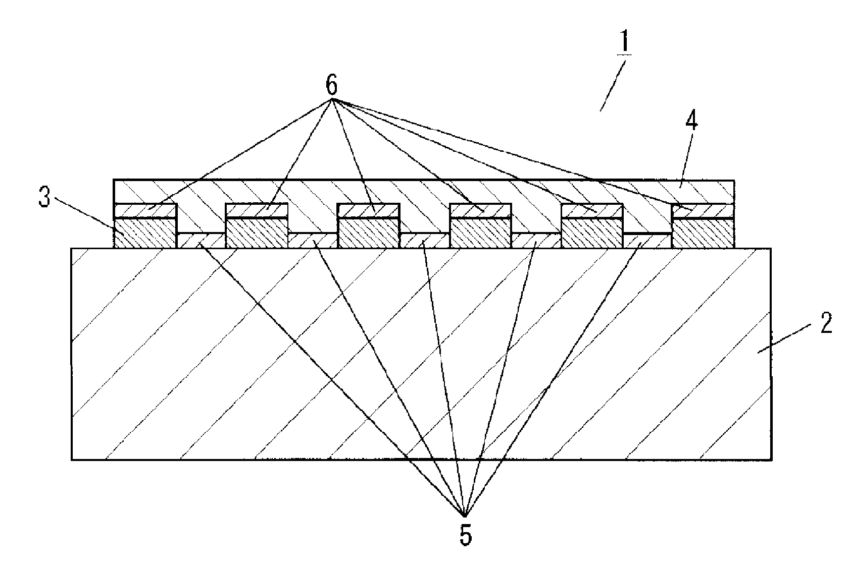
[0023]FIG. 1 is a schematic cross-sectional view of an acoustic wave device in accordance with an exemplary embodiment of the present invention, and particularly, illustrates a cross section of the device along a direction perpendicular to a direction in which an interdigital transducer (IDT) electrode extends.

[0024]Acoustic wave device 1 shown in FIG. 1 includes piezoelectric substrate 2, comb-shaped electrode 3 formed on piezoelectric substrate 2 and exiting a Rayleigh wave as a main acoustic wave, first dielectric film 4 formed above piezoelectric substrate 2 to cover comb-shaped electrode 3. Acoustic wave device 1 further includes second dielectric film 5 provided between electrode fingers of the comb-shaped electrode and between piezoelectric substrate 2 and first dielectric film 4, and second dielectric film 6 provided above comb-shaped electrode 3 and between comb-shaped electrode 3 and first dielectric film 4. The Rayleigh wave has a wavelength X which is twice as long as pi...


PUM


Abstract

An acoustic wave device includes a piezoelectric substrate, a comb-shaped electrode formed on the piezoelectric substrate and configured to excite a Rayleigh wave as a main acoustic wave, a first dielectric film formed above the piezoelectric substrate to cover the comb-shaped electrode, and a second dielectric film having a portion provided between electrode fingers of the comb-shaped electrode and a portion provided above the comb-shaped electrode. The portion provided between the electrode fingers is provided between the piezoelectric substrate and the first dielectric film. The portion provided above the comb-shaped electrode is provided between the comb-shaped electrode and the first dielectric film. A speed of a transverse wave propagating through the first dielectric film is lower than a speed of the Rayleigh wave excited by the comb-shaped electrode. A speed of a transverse wave propagating through the second dielectric film is higher than the speed of Rayleigh wave excited by the comb-shaped electrode.

Description

[0001]This application is a continuation-in-part of International Application PCT / JP2013 / 004546, filed on Jul. 26, 2013, the contents of which are incorporated herein by referenceTECHNICAL FIELD The present disclosure relates to an acoustic wave device and an antenna duplexer using the acoustic wave device.BACKGROUND ART[0002]FIG. 10 is a schematic cross-sectional view of conventional acoustic wave device 101. Acoustic wave device 101 includes piezoelectric substrate 102, comb-shaped electrode 103 formed on piezoelectric substrate 102, and dielectric film 104 formed above substrate 102 for covering comb-shaped electrode 103. Comb-shaped electrode 103 is configured to exciting a Rayleigh wave having wavelength X as a main acoustic wave,[0003]Dielectric film 104 having a temperature coefficient of frequency (TCF) having a sign reverse to that of piezoelectric substrate 102 improves the TCF of acoustic wave device 101. A conventional acoustic wave device similar to acoustic wave device...

Claims


Application Information

Patent Timeline
Patent Type & Authority Applications(United States)
IPC IPC(8): H03H9/25H03H9/72
CPCH03H9/725H03H9/25H03H3/10H03H9/02102H03H9/0222
Inventor IWASAKI, TOMOHIRONAKAMURA, HIROYUKIKOMATSU, TOMOYA
Owner SKYWORKS PANASONIC FILTER SOLUTIONS JAPAN
Why Eureka
Try Eureka