Inspection device and inspection method

a technology of inspection device and inspection method, which is applied in the direction of instruments, television systems, polarizing elements, etc., can solve the problems of more time and more difficult to determine the gray-scale value of the system, and achieve the effect of enhancing the contrast of the optimal image, reducing the correction of polarizing elements, and enhancing the imag

Active Publication Date: 2014-06-19
IND TECH RES INST
View PDF2 Cites 9 Cited by
  • Summary
  • Abstract
  • Description
  • Claims
  • Application Information

AI Technical Summary

Benefits of technology

[0007]The inspection device and the inspection method according to the present disclosure utilizes two incident lights with two different polarizing configurations to generate two sets of different images in order to enhance the image. Furthermore, the inspection device and the inspection method according to the present disclosure reduce the correction of the polarizing elements and enhances the contrast of the optimal image to decrease process time.

Problems solved by technology

Therefore, it is more difficult to determine the gray-scale value, and it takes more time for the system to find the full-dark image and the optimum image contrast.

Method used


Image

  • Inspection device and inspection method
  • Inspection device and inspection method
  • Inspection device and inspection method

Examples


Embodiment Construction

[0018]The following description is of the best-contemplated mode of carrying out the disclosure. This description is made for the purpose of illustrating the general principles of the disclosure and should not be taken in a limiting sense. The scope of the disclosure is best determined by reference to the appended claims.

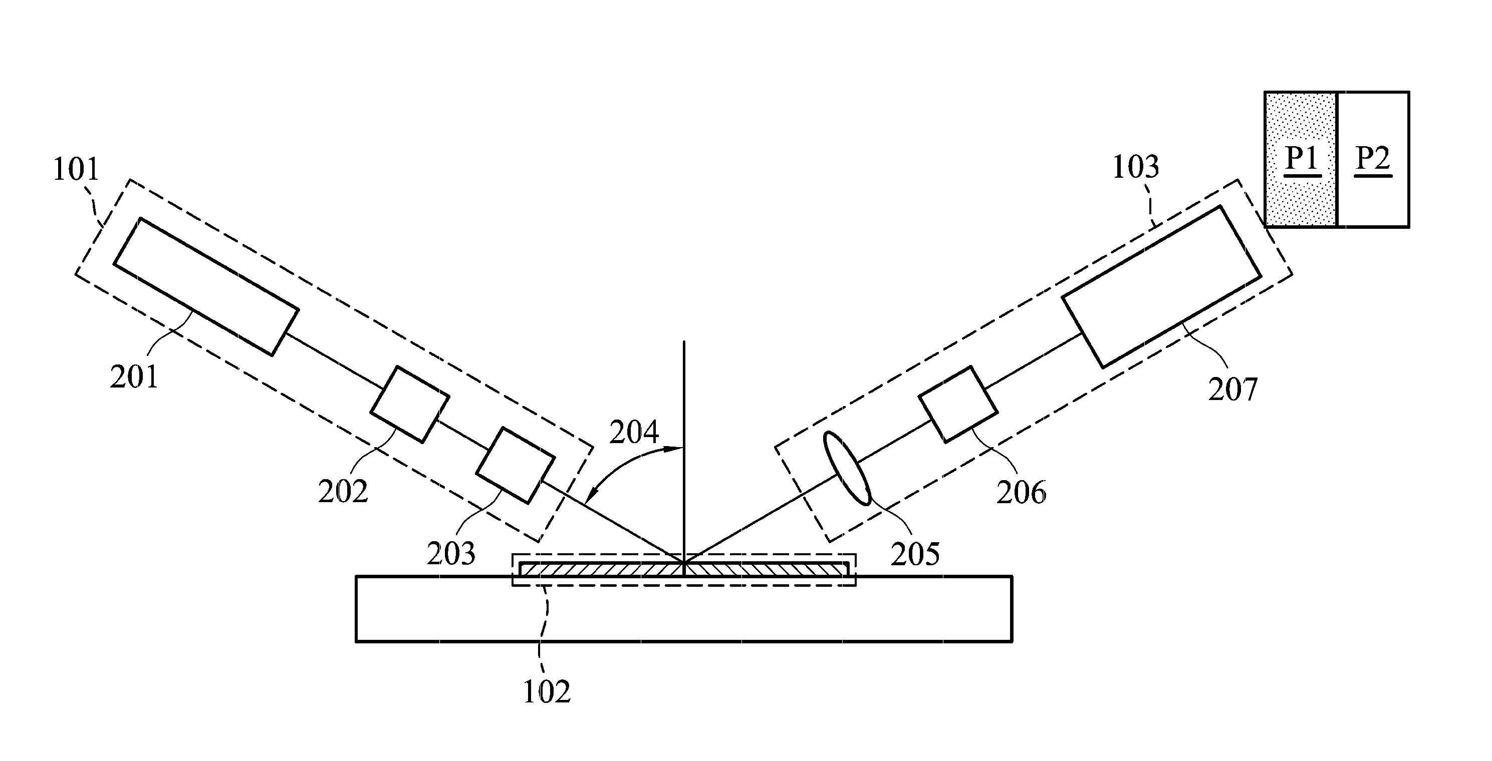
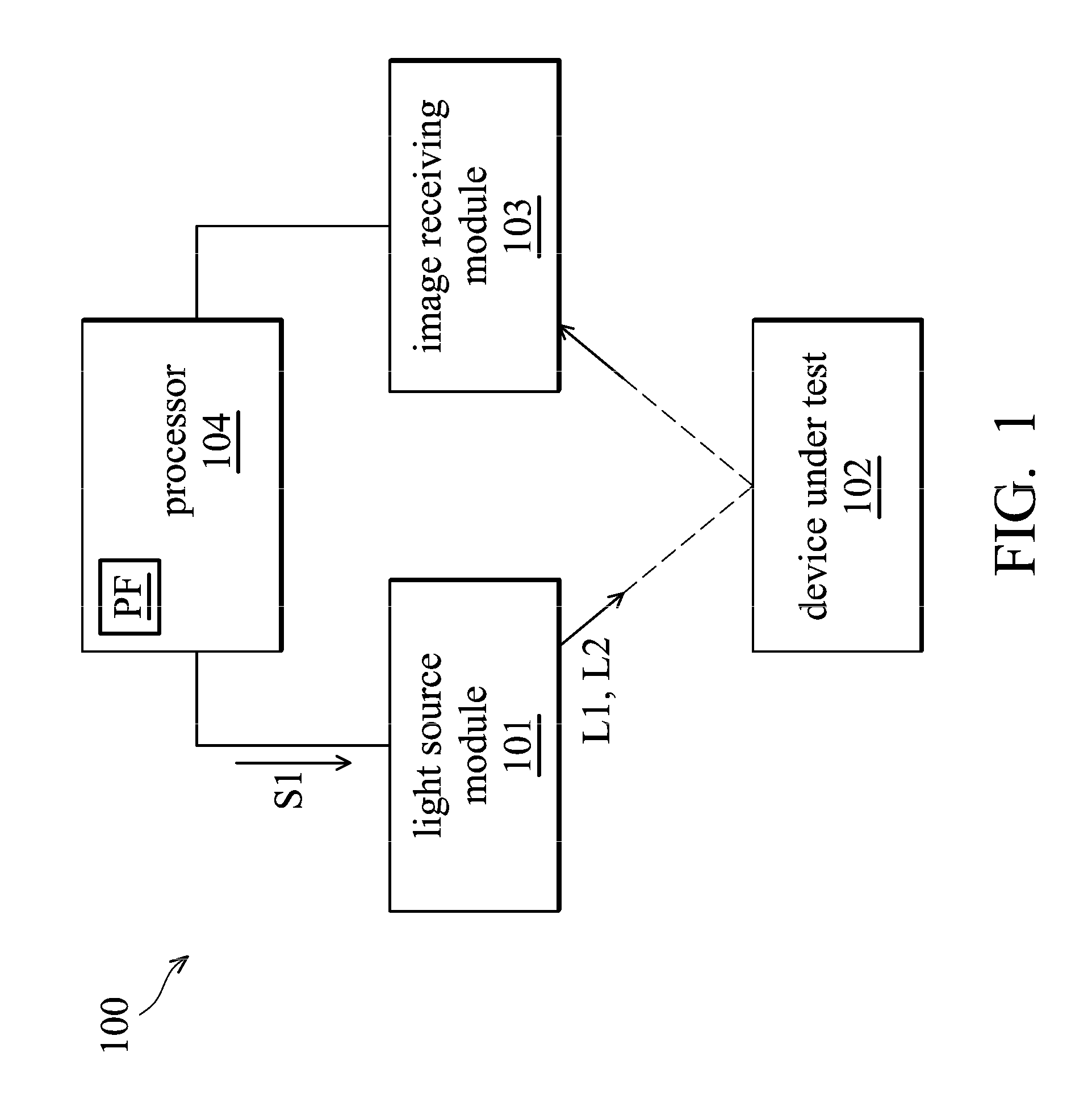
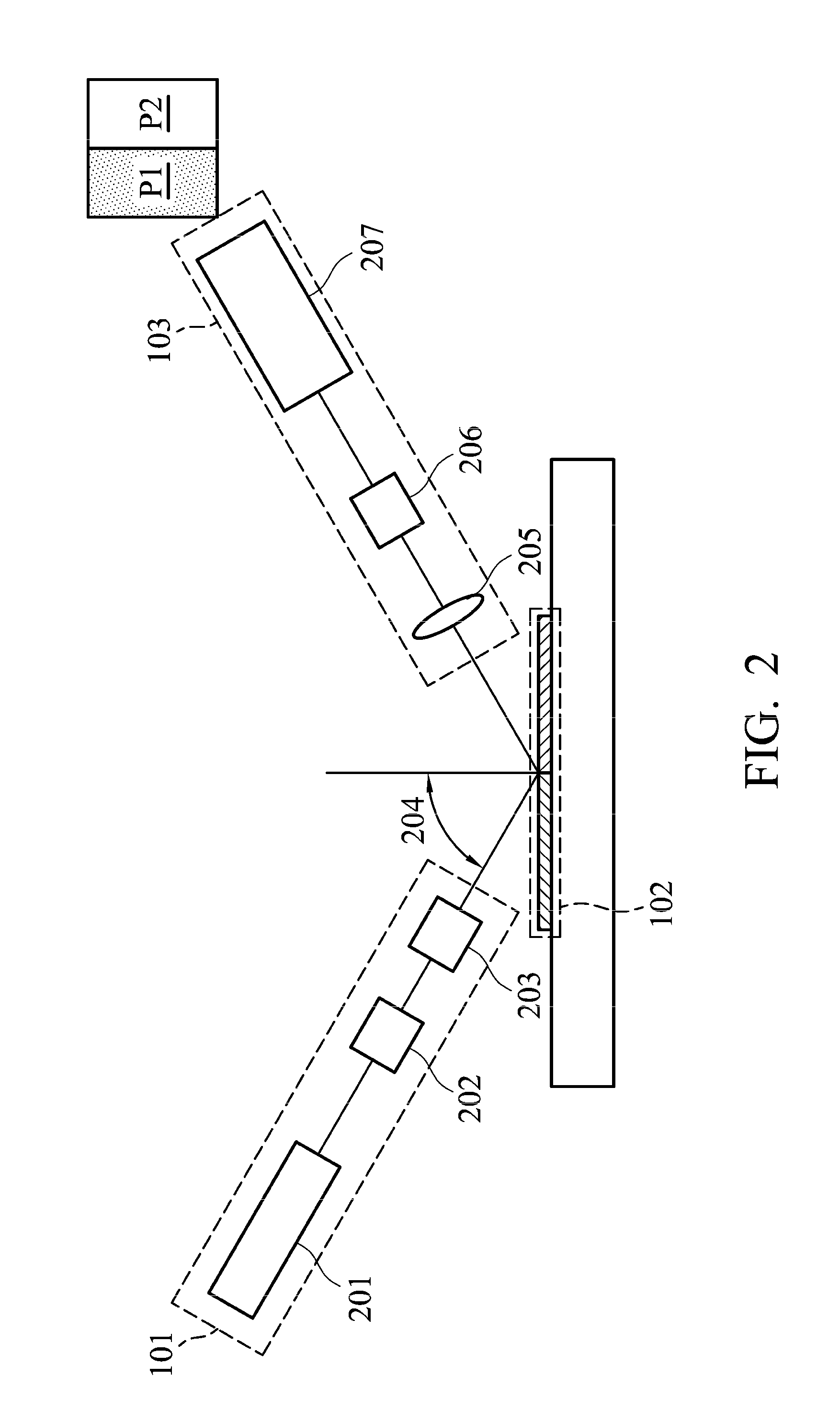
[0019]FIG. 1 is the schematic diagram of an inspection device according to the present disclosure. As shown in FIG. 1, the inspection device 100 includes a light source module 101, a device under test (DUT) 102, an image receiving module 103 and a processor 104. The inspection device 100 can be applied for the measurement of optical characteristics, semiconductor characteristics and micro-electronic characteristics. For example, the inspection device 100 is arranged to detect the physical parameters of a device under test 102, such as the thickness, the refractive index and the gray-scale value of an image of the device under test 102. The device under test 102 can ...


PUM

PropertyMeasurementUnit
wavelengthaaaaaaaaaa
incident angleaaaaaaaaaa
timeaaaaaaaaaa

Abstract

The disclosure provides an inspection device including a light source module, an image receiving module and a processing unit. The light source module emits a first incident light and a second incident light to a device under test (DUT). The image receiving module receives a first image corresponding to the DUT irradiated by the first incident light, and receives a second image corresponding to the DUT irradiated by the second incident light. The processing unit calculates the contrast ratio of the first image and the second image to obtain a high-contrast image for inspection.

Description

CROSS REFERENCE TO RELATED APPLICATIONS[0001]This application claims priority of Taiwan Patent Application No. 101147993, filed on Dec. 18, 2012, the entirety of which is incorporated by reference herein.BACKGROUND[0002]1. Field of the Disclosure[0003]The present disclosure relates to a film inspection method, and in particular, relates to a method of inspecting defects of a film by enhancing the image contrast.[0004]2. Description of the Related Art[0005]Traditionally, the method of PCSA (Polarizer Compensator Sample Analyzer) enhancing contrast for image inspection is to find the configuration of the null image (i.e., full-dark image), so that the defect region and the non-defect region display a bright gray-scale image and a dark gray-scale image. A full-dark image is arranged to enhance the image contrast of another region. The angles of the analyzer and the polarizer are rotated during operation, and the gray-scale value of one of the regions gradually decreases to the full-dar...

Claims


Application Information

Patent Timeline
Patent Type & Authority Applications(United States)
IPC IPC(8): G01N21/88G02B5/30
CPCG01N21/8806G01N21/21G01N21/9501G01N2021/8848G02B5/3066
Inventor HSIEH, YI-CHENCHIANG, CHIH-JUNGYANG, FU-CHENG
Owner IND TECH RES INST
Why Eureka
Try Eureka