Rate-based model predictive control method for internal combustion engine air path control

a technology of internal combustion engine and control method, applied in the direction of electric control, machines/engines, mechanical equipment, etc., to achieve the effect of reducing the number of regions

Inactive Publication Date: 2014-06-26
RGT UNIV OF MICHIGAN +1
View PDF6 Cites 52 Cited by
  • Summary
  • Abstract
  • Description
  • Claims
  • Application Information

AI Technical Summary

Benefits of technology

[0019]The method further includes reducing the number of regions in each of the at least one zone

Problems solved by technology

Further, each predictive controller uses integral type action that pres

Method used


Image

  • Rate-based model predictive control method for internal combustion engine air path control
  • Rate-based model predictive control method for internal combustion engine air path control
  • Rate-based model predictive control method for internal combustion engine air path control

Examples


Embodiment Construction

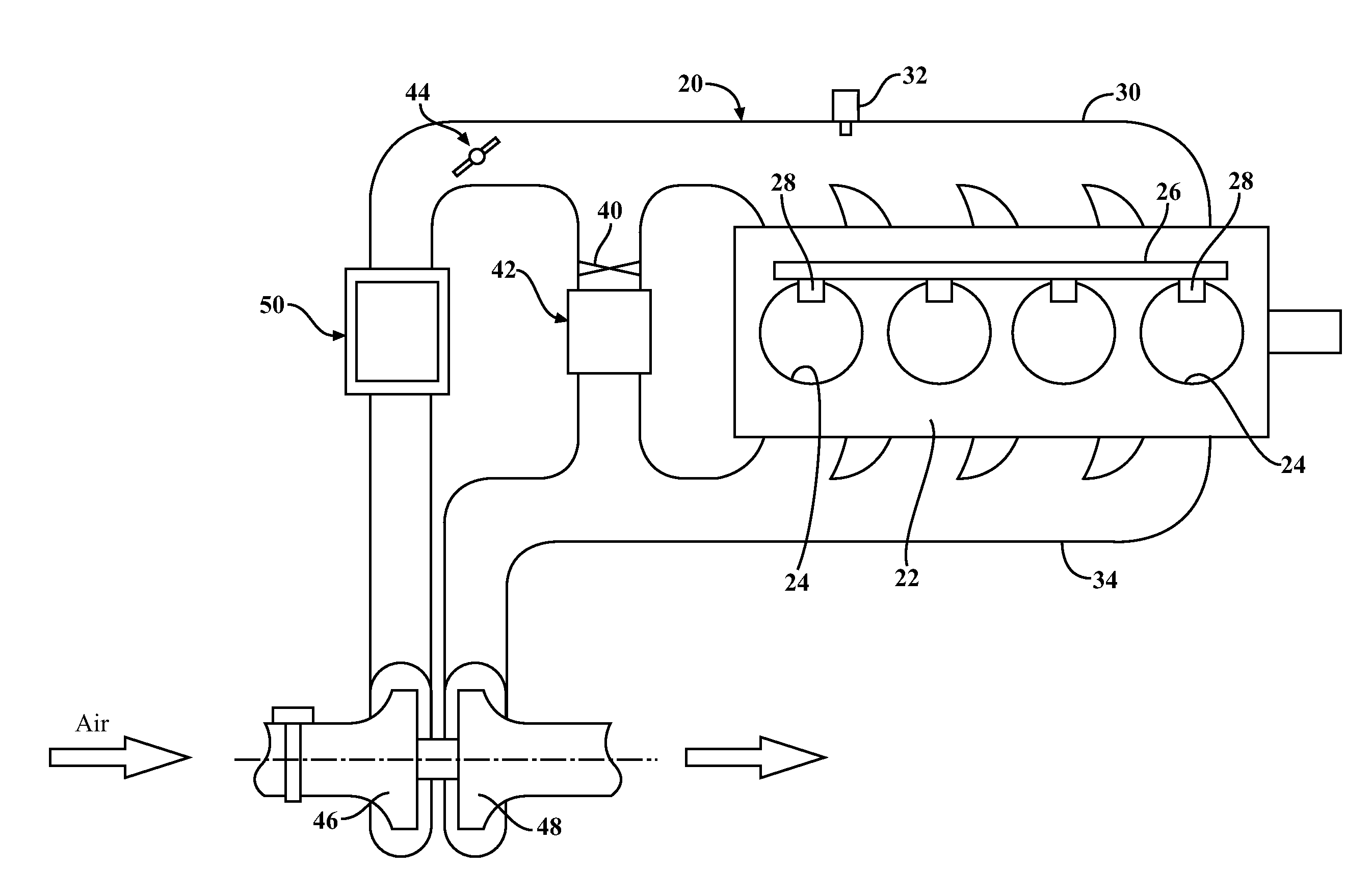
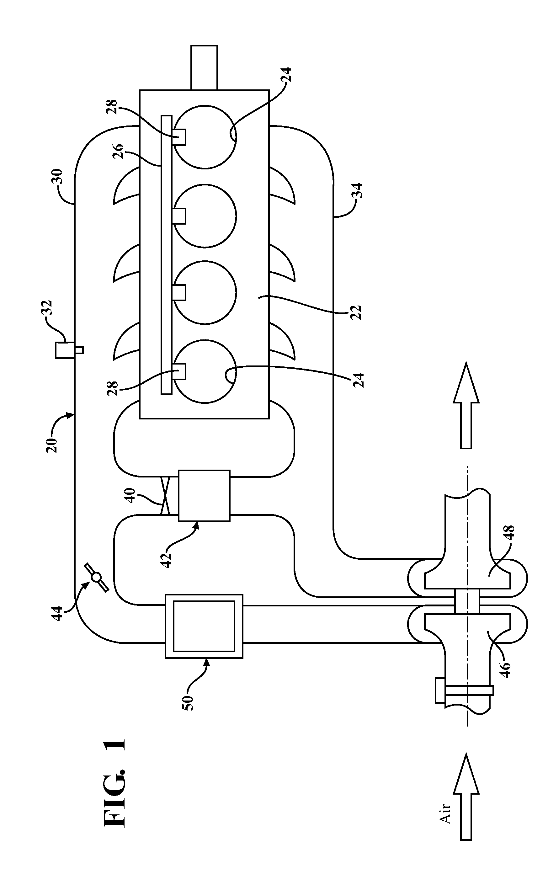
[0036]Referring now to FIG. 1, an internal combustion engine 20, described hereafter by example as a diesel engine, includes an engine block 22 housing a plurality of cylinders 24. A fuel rail 26 connected to a fuel supply, not shown, supplies diesel fuel to a plurality of fuel injectors 28 with one fuel injector provided for each cylinder 24.

[0037]An intake manifold 30 is coupled to the cylinders 24 for supplying intake air to each cylinder. An intake manifold pressure sensor 32 is coupled to the intake manifold 30 for measuring intake manifold air pressure.

[0038]An exhaust manifold 34 carries combustion gases from the cylinders 24 away from the engine block 22.

[0039]An EGR valve 40 is coupled in a bypass path between the intake manifold 30 and the exhaust manifold 34 to recirculate a portion of the exhaust gases from the exhaust manifold 34 back into the intake manifold 32 for supply to the cylinders 24. An EGR cooler 42 may be coupled in the bypass path along with the EGR valve 4...


PUM


Abstract

A rate based model predictive controller for air path control for a diesel engine regulates turbine lift and EGR valve flow rate to specified set points by coordinated control of intake manifold air pressure and EGR valve flow rate. The controller utilizes a rate-based reduced order linear model for model predictive control.

Description

BACKGROUND[0001]The present description relates, in general, to methods and controls for internal combustion engines and, more particularly, to methods for controlling diesel engines.[0002]Modern diesel engines uses variable geometry turbines (VGT) to increase the amount of air supplied to the engine cylinders. The VGT varies the angle of the turbine stator inlet vanes to change the amount of air supplied to the engine cylinders.[0003]In addition to providing optimum performance and fuel economy, modern diesel engines must also meet stringent federal regulations on emissions, particularly, particulate matter and nitrogen oxides. In order to meet all of these requirements, diesel engines with a VGT also use an exhaust gas recirculation (EGR) valve that has a variable controlled position to recirculate varying amounts of engine exhaust gases back into the engine cylinders for more complete combustion and reduced engine emissions.[0004]As the engine operates over a large range of opera...

Claims


Application Information

Patent Timeline
IPC IPC(8): F02B47/08
CPCF02B47/08F02D41/0077F02D41/1401F02D41/0007F02D2041/1412F02D2041/1434F02D41/005Y02T10/12Y02T10/40F02D2041/1416
Inventor HUANG, MIKEKOLMANOVSKY, ILYA V.
Owner RGT UNIV OF MICHIGAN
Why Eureka
Try Eureka