
Waterproof seal for electrical assemblies

a technology for electrical assemblies and sealing seals, applied in the direction of cable junctions, cable terminations, coupling device connections, etc., can solve the problems of many electrical devices prematurely failing, internal components, product failures, etc., and achieve the effect of increasing the current in the circui

Active Publication Date: 2014-06-26
D S M & T
View PDF15 Cites 14 Cited by
  • Summary
  • Abstract
  • Description
  • Claims
  • Application Information

AI Technical Summary

Benefits of technology

The invention relates to a sealing process that prevents fluids from damaging various electrical devices. The process involves creating a waterproof seal at critical points where cables are attached to connectors. The seal is made of a metal post, solder, epoxy material, bonding agent, and a coating of thermoplastic elastomer (TPE). This seal helps prevent moisture and other fluids from reaching sensitive components, preventing premature failures and potentially damaging electrical devices. The four-step process involves tinning wire strands with solder, injecting epoxy into connectors, applying a bonding agent, and finally molding PVC over all components for a complete seal.

Problems solved by technology

Liquids routinely travel through air gaps in wire and cable causing many electrical devices to prematurely fail.
Any liquid that reaches an electrical device can cause damage of the internal components, which leads to product failures.
The presence of moisture in an electrical device also can rapidly increase the current in the circuit, which in most modern appliances will cause a short circuit as the fuse is blown.

Method used


Image

  • Waterproof seal for electrical assemblies
  • Waterproof seal for electrical assemblies
  • Waterproof seal for electrical assemblies

Examples


Embodiment Construction

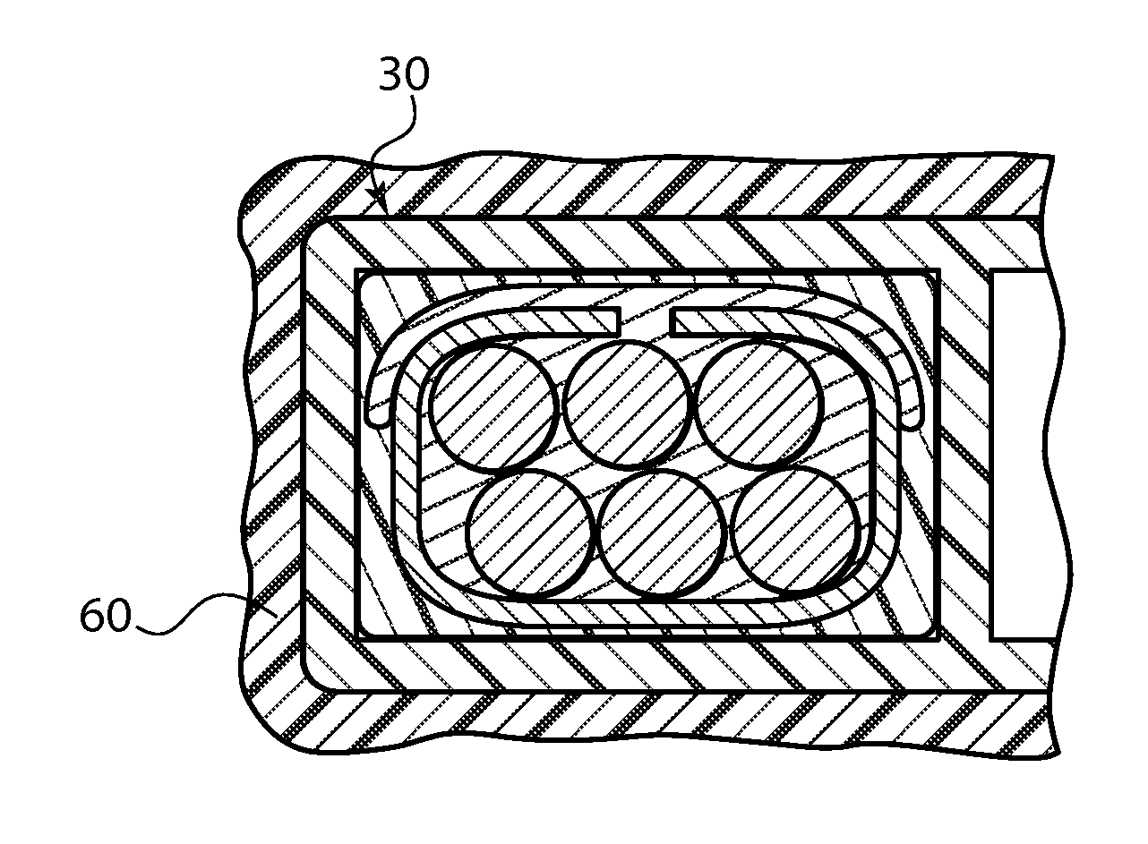
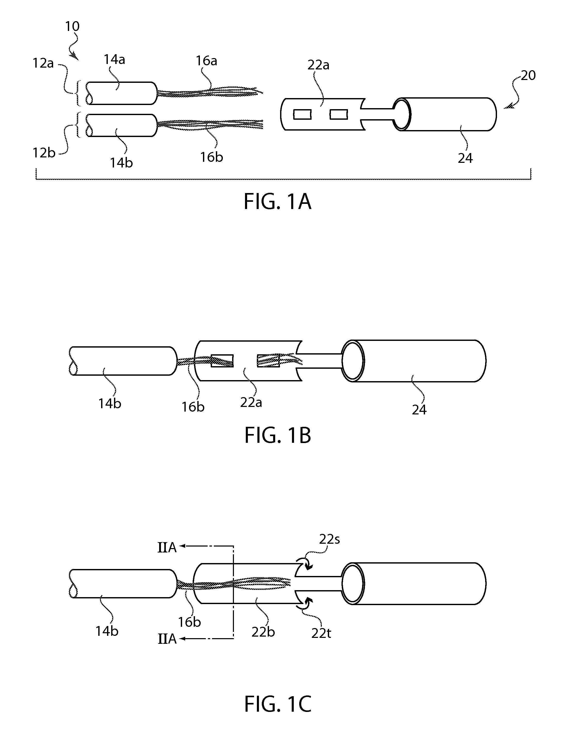
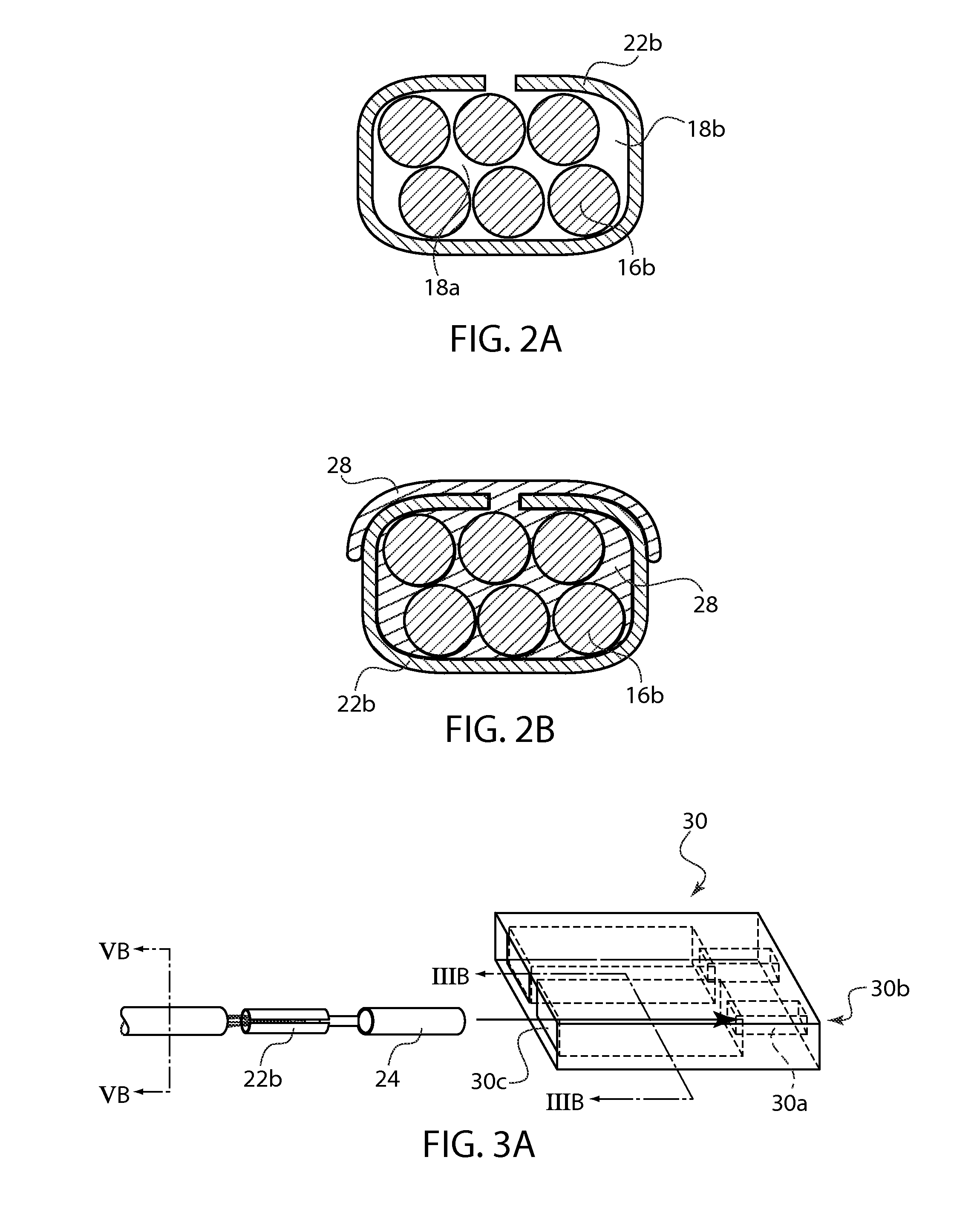
[0040]Referring now in detail to the drawings, there is shown an embodiment of the construction for the waterproof seal for electrical connectors or electrical assemblies. In FIG. 1A an electrical cable 10 is provided which includes at least one insulated conductive wires. For the sake of simplicity, one or two conductive wires will be shown in the drawings, it being understood that the waterproof seal could be duplicated for use on any number of conductive wires contained within the electrical cable. In FIG. 1A, electrical cable 10 is shown with two insulated conductive wires 12a and 12b. Removing a small section of insulation 14a, 14b exposes terminal ends 16a, 16b of the conductive wire. The terminal ends, or stripped wires, may be solid wire or stranded wires.

[0041]In order to safety and securely couple and uncouple electrical circuits, electrical cables are fitted with connectors 40. The connectors typically include a housing which contains a metal post. Metal post 20 includes ...


PUM


Abstract

A waterproof seal for electrical assemblies having conductive wires attached to a metal contact and inserted into a connector body. The conductive wires and metal contact are coated with solder to fill the gaps. The space between the soldered wires and the connector body are filled with an epoxy. The wire insulation and connector body are continuously sealed with a bonding agent. A section of wire insulation and the connector body are encased within an outer plastic jacket overmold.

Description

CROSS-REFERENCE TO RELATED APPLICATIONS[0001]This application claims priority of U.S. Provisional Application Ser. No. 61 / 735,756 filed on Dec. 11, 2012.BACKGROUND OF THE INVENTION[0002]1. Field of the Invention[0003]The present invention relates to a waterproof seal for electrical assemblies. The sealing method protects electrical devices by preventing the wicking of fluid through electrical wires. In this case, the sealing is in the form of a 4-step connector sealing process, which creates an airtight, and more importantly a watertight seal.[0004]2. The Prior Art[0005]Other types of sealing methods are known in the art. For example, sealing methods for electrical connectors may be disclosed in the following U.S. patents: U.S. patent application Ser. No. 13 / 300,182 to Rowland on May 23, 2013; U.S. Pat. No. 7,431,602 to Corona issued on Apr. 21, 2005; U.S. Pat. No. 6,444,914 issued to Su on Sep. 3, 2002; U.S. Pat. No. 6,069,320 to Rocci et al issued on May 30, 2000; U.S. Pat. No. 4,...

Claims


Application Information

Patent Timeline
IPC IPC(8): H02G15/04
CPCH02G15/04H01R4/02H01R13/5205H01R13/521H01R43/24H02G15/003
Inventor CORONA, SERGIO
Owner D S M & T
Learn More