
Engine mounting structure for reducing vibration

a technology for mounting structures and engines, applied in the direction of machine supports, jet propulsion mounting, other domestic articles, etc., can solve the problems of deteriorating salability and driving performance of vehicles, deteriorating nvh performance of vehicles, and 3 cylinder engines have some drawbacks compared to a typical 4-cylinder engine, so as to reduce horizontal rigidity, reduce vibration, and reduce vibration during idle

Active Publication Date: 2014-06-26
HYUNDAI MOTOR CO LTD
View PDF3 Cites 3 Cited by
  • Summary
  • Abstract
  • Description
  • Claims
  • Application Information

AI Technical Summary

Benefits of technology

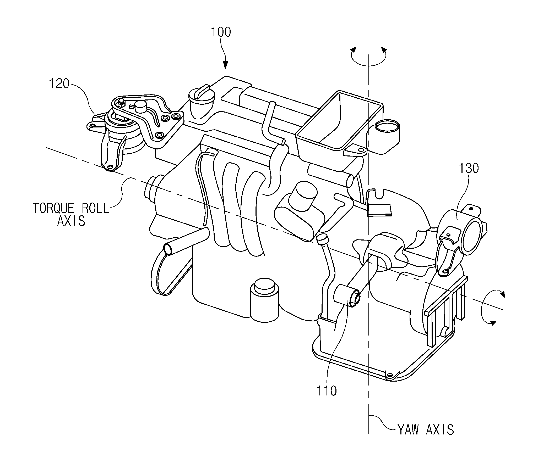
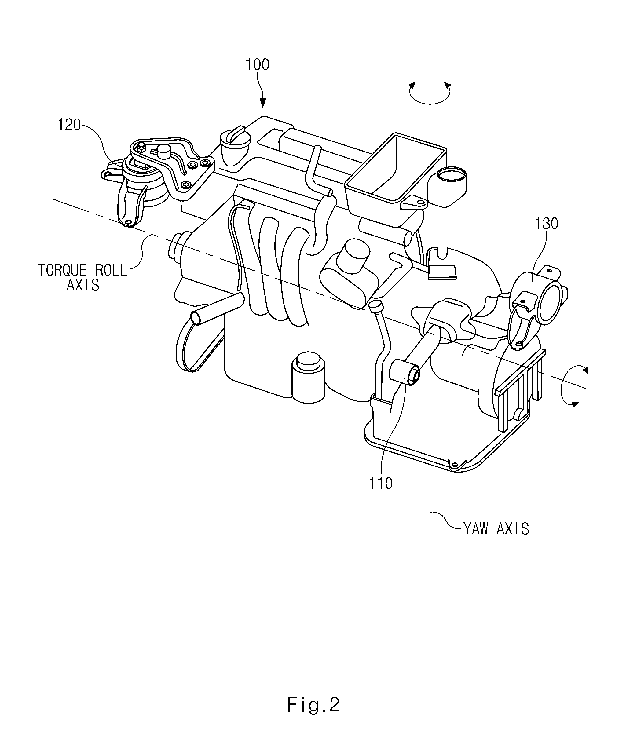
The present invention is an engine mounting structure that reduces vibration during idling. It includes a mass forming an outer balancer, a roll mount positioned on a virtual yaw axis, an engine mount mounted on a virtual torque roll axis, and a transmission mount also mounted on a virtual torque roll axis. The entire excitation of the engine is generated along the virtual yaw axis, and the roll mount reduces horizontal rigidity. The engine mount and transmission mount are damping mounts in a front and rear direction for reducing a spring value at an idle frequency, and orifice plates are formed in the engineer mount and transmission mount for damping in the front and rear direction. This structure helps to reduce vibration and provide a smoother ride for the engine.

Problems solved by technology

However, currently, 3-cylinder engines have some drawbacks compared to a typical 4-cylinder engine due to the amount of vibration they produce.
Although some engine mounts for reducing vibration and noise generated by the engine have been developed, a significant amount of vibration is still generated in yaw and roll moments at the time of idle vibration to deteriorate NVH performance of the vehicle, such that salability and driving performance of the vehicle is also deteriorated as a result of the vehicles lack-luster NVH performance.

Method used


Image

  • Engine mounting structure for reducing vibration
  • Engine mounting structure for reducing vibration
  • Engine mounting structure for reducing vibration

Examples


Embodiment Construction

[0018]It is understood that the term “vehicle” or “vehicular” or other similar term as used herein is inclusive of motor vehicles in general such as passenger automobiles including sports utility vehicles (SUV), buses, trucks, various commercial vehicles, watercraft including a variety of boats and ships, aircraft, and the like, and includes hybrid vehicles, electric vehicles, combustion, plug-in hybrid electric vehicles, hydrogen-powered vehicles and other alternative fuel vehicles (e.g. fuels derived from resources other than petroleum).

[0019]Exemplary embodiments of the present invention will be described in detail with reference to the accompanying drawings.

[0020]An engine mounting structure configured to reduce vibration according to an exemplary embodiment of the present invention is configured to include an engine 100, a roll mount 110 positioned at a yaw axis of the engine 100, an engine mount 120 mounted at one end of a torque roll axis of the engine 100, and a transmission...


PUM


Abstract

Disclosed herein is an engine mounting structure for reducing vibration. In particular, an engine having a mass is mounted to a damper pulley or a drive plate thereof to form an outer balancer. A roll mount is positioned on a virtual yaw axis after the virtual yaw axis is set in the engine, and an engine mount is mounted to one end of a virtual torque roll axis after the virtual torque roll axis is set in the engine. Furthermore, a transmission mount is mounted to the other end of the virtual torque roll axis. Therefore, the mounts are mounted to the engine to reduce vibration at the time of idle vibration, thereby making it possible to improve NHV performance of a vehicle and increase salability and driving convenience of a driver.

Description

CROSS-REFERENCE TO RELATED APPLICATION[0001]This application is based on and claims priority from Korean Patent Application No. 10-2012-0153498, filed on Dec. 26, 2012 in the Korean Intellectual Property Office, the disclosure of which is incorporated herein in its entirety by reference.BACKGROUND OF THE INVENTION[0002]1. Field of the Invention[0003]The present invention relates to an engine mounting structure for reducing vibration, and more particularly, to an engine mounting structure for reducing vibration during idle vibrations via the engine mounts.[0004]2. Description of the Prior Art[0005]With an increase in a demand for compact vehicles, the size of an engine has become smaller and as such vehicles in which a 3-cylinder engine is mounted therein have become increasingly popular. However, currently, 3-cylinder engines have some drawbacks compared to a typical 4-cylinder engine due to the amount of vibration they produce. In connection with this, the greatest weakness in view...

Claims


Application Information

Patent Timeline
Patent Type & Authority Applications(United States)
IPC IPC(8): B60K5/12
CPCB60K5/1266B60K5/1241B60K5/1225B60K5/1216B60K5/00B60K5/12
Inventor KIM, YONG JOO
Owner HYUNDAI MOTOR CO LTD
Learn More