Systems and methods for dimming of a light source

a technology of lighting system and dimming method, which is applied in the direction of electric variable regulation, process and machine control, instruments, etc., can solve the problems of compatibility with existing dimming circuits and the character of non-incandescent lamps that may not be purely resistive, so as to improve the dimming linearity, and improve the dimming performance

Active Publication Date: 2014-06-26
KORRUS INC
View PDF8 Cites 83 Cited by
  • Summary
  • Abstract
  • Description
  • Claims
  • Application Information

AI Technical Summary

Benefits of technology

[0006]The present disclosure describes methods and systems for improving the dimming performance of lighting systems, such as the improvement of dimming LED lamps that are dimmed from standard external dimming devices. Methods and systems for improving dimming performance include a fast startup override facility, a dynamic RC selection facility, an active N-level bleeder facility, a dimmer-type detection facility, an improved dimming linearity through symmetrical phase cutting facility, and a flicker reduction facility. The fast startup override facility may override information of a dimming function (e.g., such as through a dimming pin of an LED driver) of the lamp's electronics through forcing the lamp electronics to operate with a higher than normal duty cycle to ensure the lamp electronics can deliver higher than normal power to an LED module during a dimming current level startup condition. The dynamic RC selection facility may allow the RC network being used in an average voltage method to have a varying response under different conditions. The active N-Level bleeder facility may reduce flickering by intelligently changing active dummy resistance loads (bleeder) to the AC line through an active N-Level bleeder facility. The syst

Problems solved by technology

However, the characteristics of the non-incandescent lamps may not be purely resistive, as in the case of an incandescent light bulb.
This, along with differences in the properties among dimming types, dictates that the compatibility with

Method used


Image

  • Systems and methods for dimming of a light source
  • Systems and methods for dimming of a light source
  • Systems and methods for dimming of a light source

Examples


Embodiment Construction

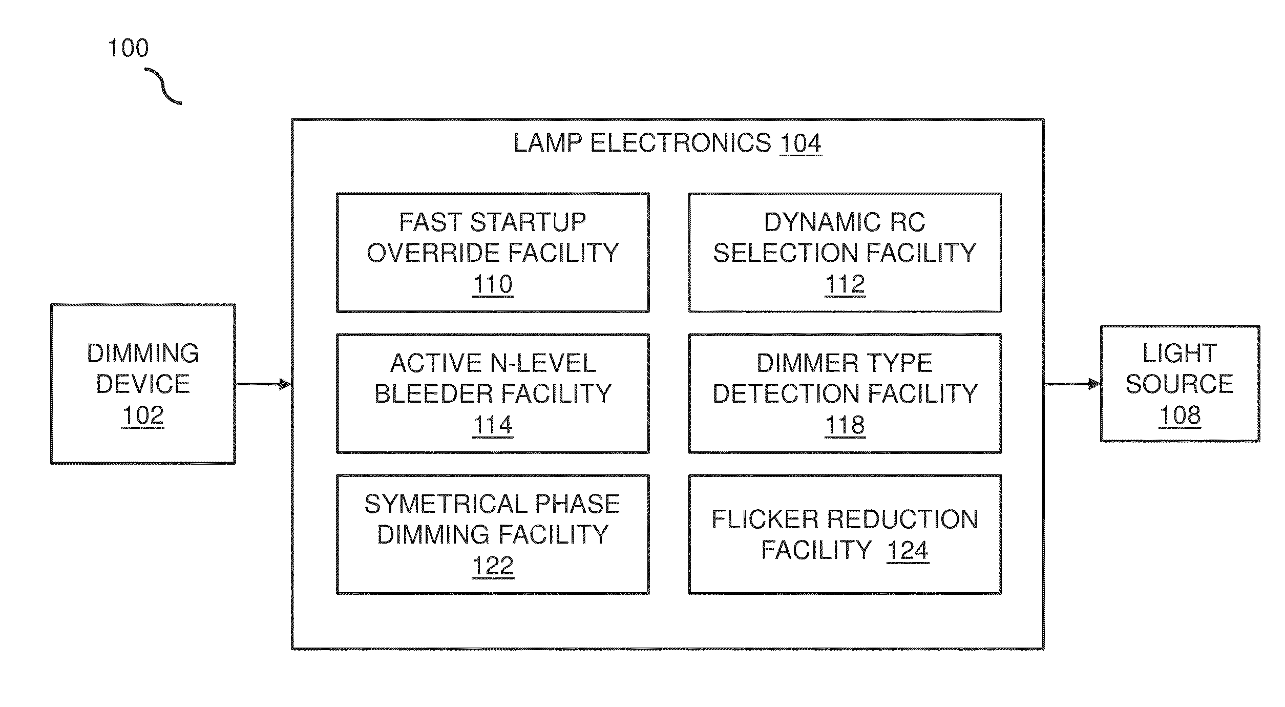
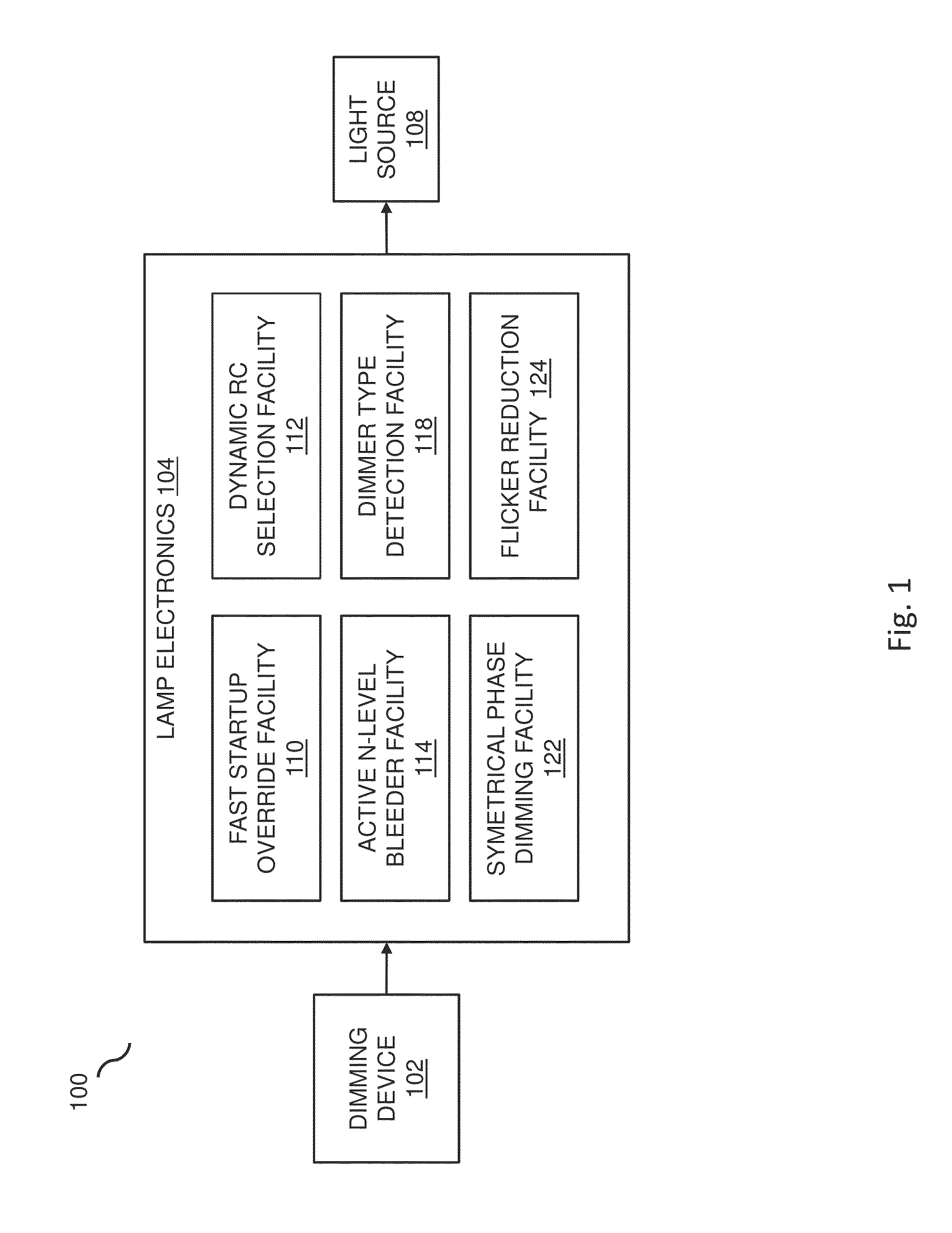
[0043]This disclosure provides embodiments that improve the performance for dimming of a light source. FIG. 1 presents a block diagram of a dimmable lamp 100, such as including lamp electronics 104 with at least one of a fast startup override facility 110, dynamic RC selection facility 112, active N-level bleeder facility 114, dimmer type detection facility 118, symmetrical phase dimming facility 122, flicker reduction facility 124, and the like, for improving the dimming performance of the lamp when varying the brightness of the light source 108 through use of a dimming device 102. The dimmable lamp 100 may be a ‘light bulb’ that mounts into a lighting fixture, a lighting fixture, and the like. The lamp may be utilized with various types of dimming devices 102, such as including leading or trailing edge dimmable lighting drivers by input by any wired and wireless input signal, such as utilizing a variable resistor, 0-10V lighting control, a Digital Addressable Lighting Interface (D...


PUM


Abstract

In embodiments, improved capabilities are described for dimming performance of lighting methods and systems, such as the improvement of dimming LED lamps that are dimmed from standard external dimming devices. Methods and systems for improving dimming performance include a fast startup override facility for overriding a default dimming function of the lamp's electronics through forcing the lamp electronics to operate with a higher than normal duty cycle to ensure the lamp electronics can deliver higher than normal power to an LED module during a dimming current level startup condition. Dimming facilities may also include a dynamic RC selection facility, an active N-level bleeder facility, a dimmer-type detection facility, an improved dimming linearity through symmetrical phase cutting facility, and a flicker reduction facility.

Description

CROSS-REFERENCE TO RELATED APPLICATIONS[0001]This application claims the benefit of the following provisional applications, which are hereby incorporated by reference in their entirety: U.S. Provisional Application 61 / 737,957 filed Dec. 17, 2012, and U.S. Provisional Application 61 / 763,268 filed Feb. 11, 2013.BACKGROUND[0002]1. Field[0003]This invention relates to light sources, and more particularly to the dimming of light sources and lighting fixtures thereof.[0004]2. Description of Related Art[0005]Dimming of a light source has wide applications in many areas. The light sources may be incandescent, fluorescent, LEDs, and the like. Nowadays, non-incandescent lamps are becoming popular, where ideally a replacement lamp should be compatible with existing electrical circuits, including existing dimming circuits such as leading edge and trailing edge type dimming circuits. However, the characteristics of the non-incandescent lamps may not be purely resistive, as in the case of an inca...

Claims


Application Information

Patent Timeline
IPC IPC(8): H05B33/08H05B37/02H05B44/00
CPCH05B45/10H05B45/37H05B45/3575H05B45/31H05B45/36H05B45/315Y02B20/30Y02B20/40
Inventor LI, HANG FAIYEE, PING HOCHAN, HOI KUENWONG, CHIU HO
Owner KORRUS INC
Why Eureka
Try Eureka