Laser beam pattern projector

a laser beam and pattern technology, applied in the field of laser beam pattern projectors, can solve the problems of limited effectiveness of existing directed energy systems utilizing lasers, ineffective existing systems when applied to large geographic areas, and limited application rang

Active Publication Date: 2014-06-26
DOUBLESHOT
View PDF4 Cites 54 Cited by
  • Summary
  • Abstract
  • Description
  • Claims
  • Application Information

AI Technical Summary

Problems solved by technology

In certain situations, however, existing directed energy systems utilizing lasers may be of limited effectiveness.
For example, existing system may be ineffective when applied to large geographic areas.
The first case requires a very high power source; while the second approach is limited by the time required to scan a large area with a single spot or line.
The scan time may limit dwell time and may require impractical rates of motion for large areas or multiple systems.
As a result, the ability to neutralize an undisclosed threat in a broad area is limited by the operator.
Further, sufficient dwell time may not be available to cause the desired effects of aversion or disruption.
Some existing systems have difficulty denying visual access across target areas having varying geographic and structural conditions.
These systems, however, may create eye safety concerns when used at closer distances, such as in narrow corridors or within a building.

Method used


Image

  • Laser beam pattern projector
  • Laser beam pattern projector
  • Laser beam pattern projector

Examples


Embodiment Construction

[0018]Reference will now be made in detail to embodiments, examples of which are illustrated in the accompanying drawings. Wherever possible, the same reference numbers will be used throughout the drawings to refer to the same or like parts.

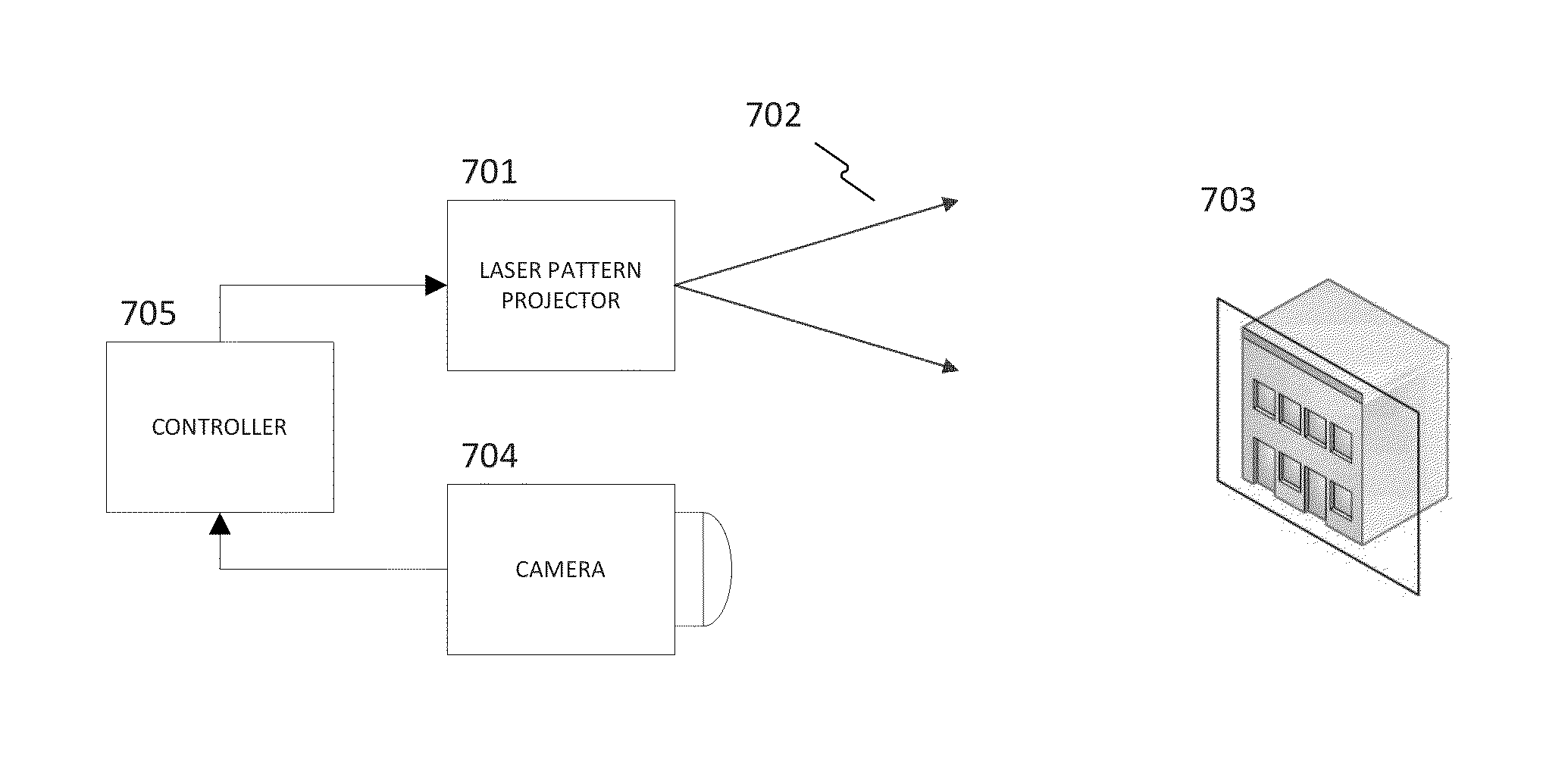
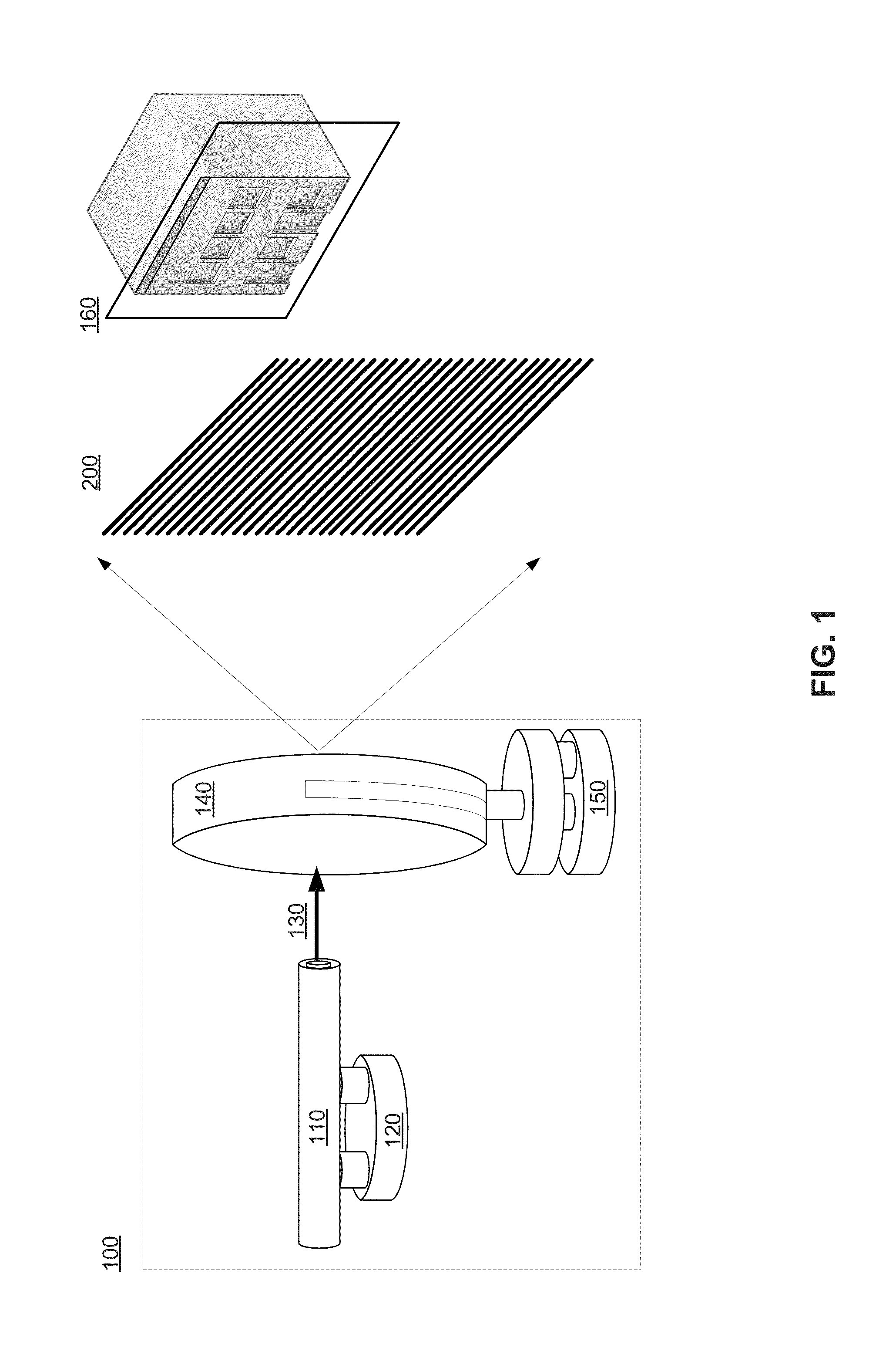
[0019]FIG. 1 shows a block diagram illustrating components in system 100 for creating an area of denied visual access. As shown in FIG. 1, system 100 comprises a light source 110 and a diffractive optic element 140. Light source 110 may be, for example, a laser or a partially coherent light source. Lasers may be, for example, a laser diode, a solid state laser, or a gas laser. In certain embodiments, light source 110 may be a green diode-pumped solid state (DPSS) laser. DPSS lasers may operate in continuous wave (CW), quasi-CW, analog modulated, or pulsed mode. The laser wavelength may be chosen based on the application, with exemplars of near UV or visible for biological visual systems (for example, human eyes), and the full range of optical wav...


PUM

PropertyMeasurementUnit
wavelengthsaaaaaaaaaa
wavelengthaaaaaaaaaa

Abstract

Methods and systems consistent with some embodiments presented provide methods for denying visual access to a first area from a target area. In some embodiments, methods for denying visual access from a target area may include generating a structured light pattern and projecting the structured light pattern from onto the target area. Reflections and retroreflections from the target area can indicate the presence of sensors. Characterization of one or more sensors in the target area based on the reflections and retroreflections can be performed. Parameters of the structured light pattern, such as color content, amplitude, pattern, and movement of the pattern, can be adjusted based on the type of sensor detected.

Description

CROSS-REFERENCE TO RELATED APPLICATIONS[0001]This application is a continuation-in-part of U.S. patent application Ser. No. 12 / 243,829, filed Oct. 1, 2008, which claims the benefit of priority of U.S. Provisional Application No. 60 / 976,796, filed Oct. 2, 2007, entitled “Laser Beam Pattern Projector,” the disclosure of which is expressly incorporated herein by reference in its entirety.BACKGROUND[0002]1. Technical Field[0003]Embodiments consistent with the presently-claimed invention are related to laser projection systems and, in particular, to methods and systems for creating an area of denied visual access. Embodiments are further related to characterizing sensors detected by reflection and retroreflection of the projected laser pattern.[0004]2. Discussion of Related Art[0005]Non-lethal directed energy systems are increasingly used by law enforcement because of their ability to reduce fatalities and collateral damage. Some directed weapon systems use electromagnetic energy, such a...

Claims


Application Information

Patent Timeline
Patent Type & Authority Applications(United States)
IPC IPC(8): F41H13/00G01N21/55
CPCG01N21/55F41H13/0056F41G3/14F41H3/00F41H11/02F41H13/005G01S17/88
Inventor SCOTT, MILES L.SHULMAN, ALAN
Owner DOUBLESHOT
Why Eureka
Try Eureka