Apparatus for optical see-through head mounted display with mutual occlusion and opaqueness control capability

a technology of optical see-through and head-mounted displays, which is applied in the direction of panoramic photography, magnifying glasses, instruments, etc., can solve the problems of loss of see-through view, image lag, and degradation of the image quality of the see-through view, and achieve the effect of reducing the offset of the viewpoin

Active Publication Date: 2014-06-26
MAGIC LEAP
View PDF0 Cites 782 Cited by
  • Summary
  • Abstract
  • Description
  • Claims
  • Application Information

AI Technical Summary

Benefits of technology

[0007]This invention concerns an optical see-through head mounted display (OST-HMD) device with opaqueness control and mutual occlusion capability, The display system typically comprises of a virtual view path for viewing a displayed virtual image and a see-through path for viewing an external scene in the real world. In the present invention, the virtual view path includes a miniature image display unit for supplying virtual image content and an eyepiece through which a user views a magnified virtual image. The see-through path comprises of an objective optics to directly capture the light from the external scene and firm at least one intermediate image, a spatial light modular (SLM) placed at or near an intermediate image plane in the see-through path to control and modulate the opaqueness of the see-through view, and an eyepiece optics through which the modulated see-through view is seen by the viewer. In the see-through path, the objective optics and eyepiece together act as a relay optics for passing the light from the real world to viewer's eye. To achieve a compact form factor and reduce the viewpoint offset, the see-through path is folded into two layers through several reflective surfaces, a front layer accepting the incoming light from an external scene and a back layer coupling the light captured by the front layer into a viewer's eye. The see-through path is merged with the virtual image path by a beamsplitter so that the same the eyepiece is shared by both paths for viewing displayed virtual content and the modulated see-through image. The microdisplay and the SLM are optically conjugate to each other through the beamsplitter, which makes the pixel level occlusion manipulation possible. In the present invention, the eyepiece, the objective optics, or both may be rotationally symmetric lenses or non-rotationally symmetric freeform optics. In one of its significant aspects, the present invention may utilize freeform optical technology in eyepiece optics, objective optics or both to achieve a compact and lightweight OCOST-HMD design.

Problems solved by technology

The major drawbacks of the video see-through approach include: degradation of the image quality of the see-through view; image lag due to processing of the incoming video stream; potentially loss of the see-through view due to hardware / software malfunction.
Developing optical see-through HMDs, however, confronts complicated technical challenges.
One of the critical issues lies in that the virtual views in an OST-HMD appear “ghost-like” and are floating in the real world due to the lack of the occlusion capability. FIG. 1 shows a comparison illustration of the augmented view seen through a typical OST-HWID (FIG. 1a) and the augmented view seen through an occlusion capable OST-HMD (OCOST-HMD) system (FIG. 1b), In the figure, a virtual car model is superimposed on a solid platform which represents a real object.
Without proper occlusion management as shown in FIG. 1a, in a typical AR view, the car is mixed with the platform and it is difficult to distinguish the depth relationship of the car and the platform.
Not only because of the number of elements being used, but also more importantly due to the rotationally symmetric nature of the optical systems, the existing occlusion-capable OST-HMDs have a helmet-like, bulky form factor.
They have been used exclusively in laboratory environments due to the heavy weight and cumbersome design.
The cumbersome, helmet-like form factor prevents the acceptance of the technology for many demanding and emerging applications.

Method used


Image

  • Apparatus for optical see-through head mounted display with mutual occlusion and opaqueness control capability
  • Apparatus for optical see-through head mounted display with mutual occlusion and opaqueness control capability
  • Apparatus for optical see-through head mounted display with mutual occlusion and opaqueness control capability

Examples


Embodiment Construction

[0037]The embodiments according to the present invention will be fully described with respect to the attached drawings. The descriptions are set forth in order to provide an understanding of the invention. However, it will be apparent that the invention can be practiced without these details. Furthermore, the present invention may be implemented in various forms. However, the embodiments of the present invention described below shall not be constructed as limited to the embodiments set forth herein. Rather, these embodiments, drawings and examples are illustrative and are meant to avoid obscuring the invention.

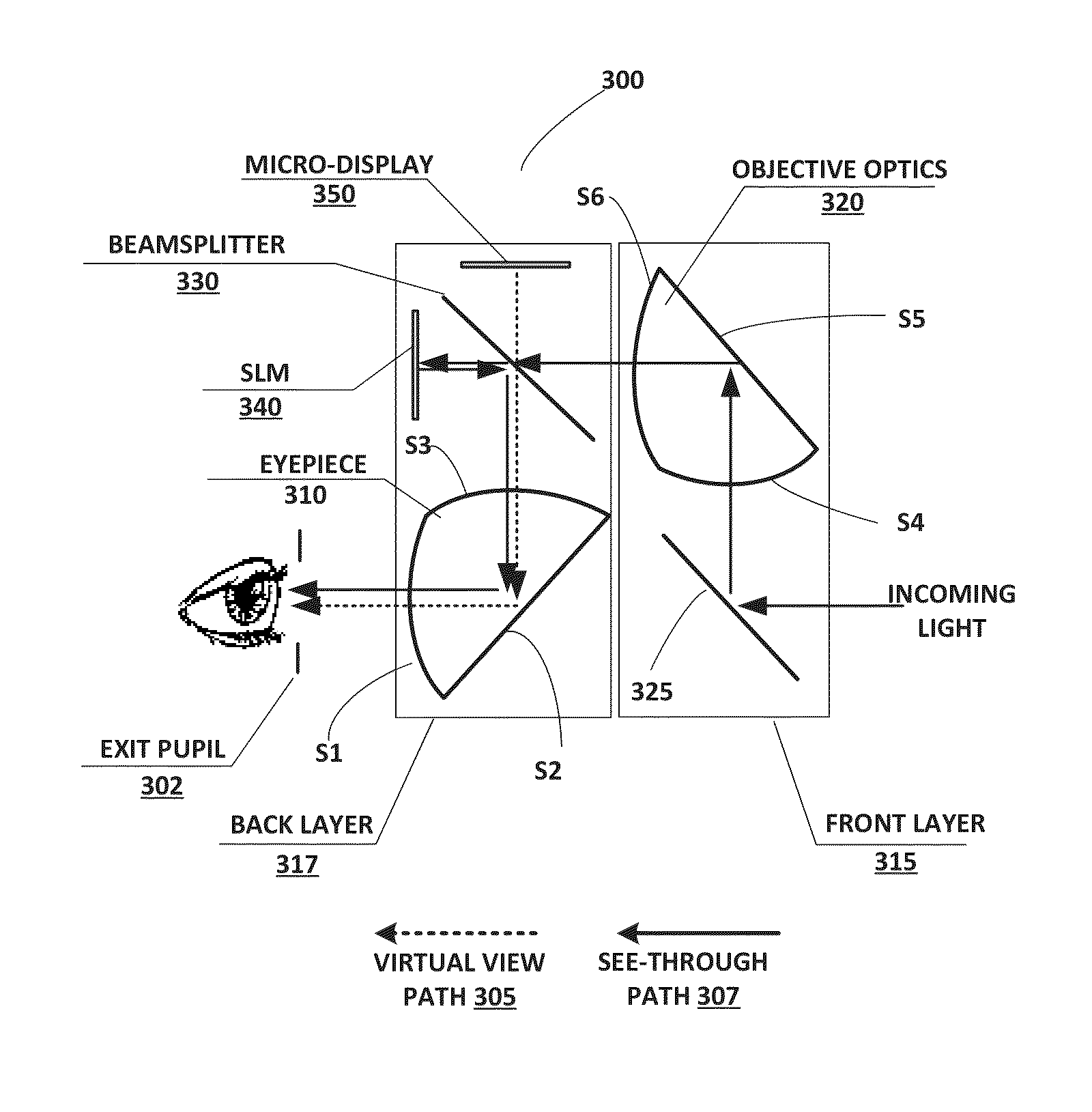
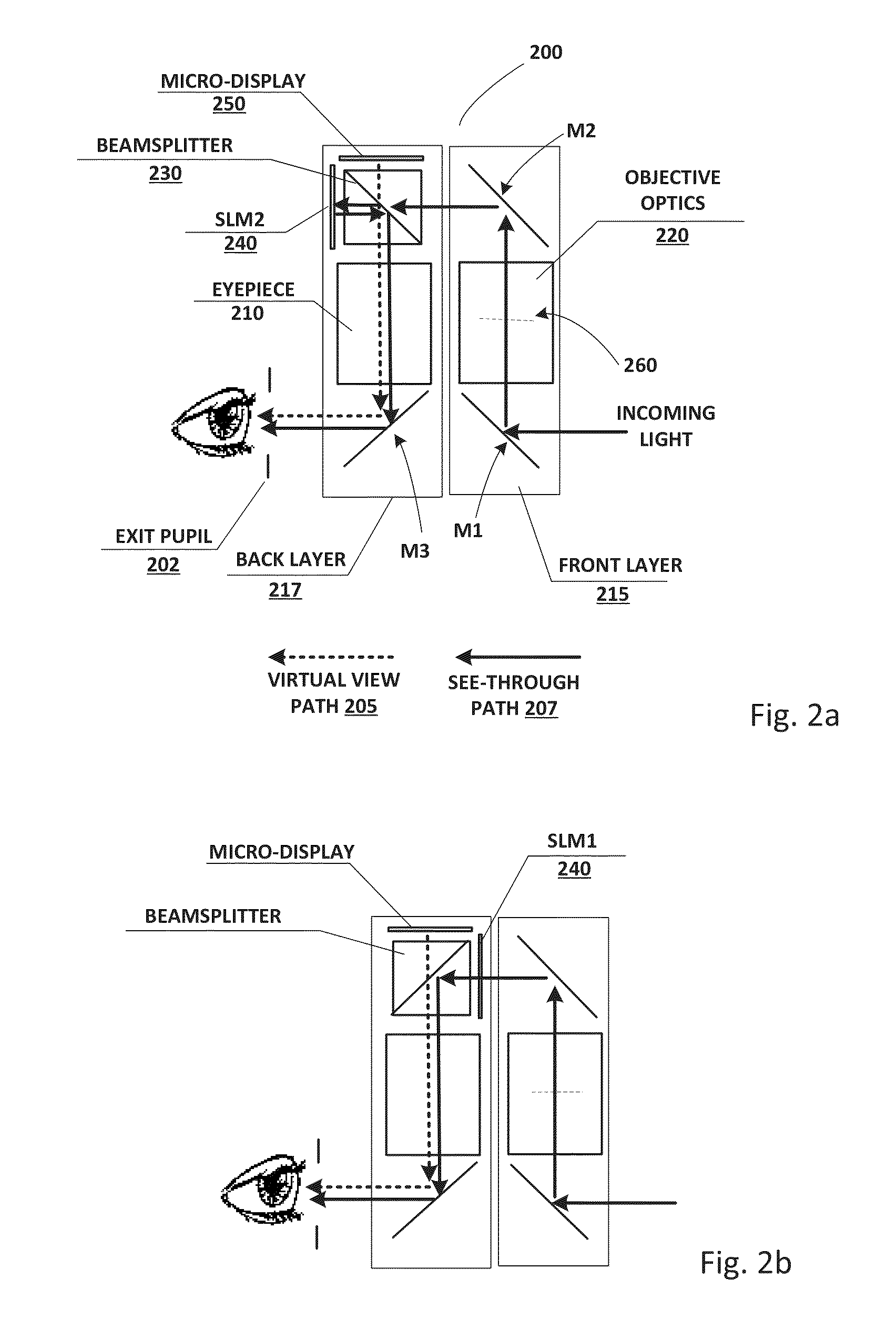
[0038]An occlusion capable optical see-through head-mounted display (OCOST-HMD) system typically comprises of a virtual view path for viewing a displayed virtual image and a see-through path for viewing an external scene in the real world. Hereafter the virtual image observed through the virtual view path is referred to as the virtual view and the external scene observed throu...


PUM


Abstract

The present invention comprises a compact optical see-through head-mounted display capable of combining, a see-through image path with a virtual image path such that the opaqueness of the see-through image path can be modulated and the virtual image occludes parts of the see-through image and vice versa.

Description

RELATED APPLICATIONS[0001]This application claims priority to U.S. Provisional Application No. 61 / 620,574, filed on Apr. 5, 2012 and U.S. Provisional Application No. 61 / 620,581, filed on Apr. 5, 2012, the disclosures of which are incorporated herein by reference in its entirety.GOVERNMENT LICENSE RIGHTS[0002]This invention was partially made with government support under SBIR contract No. W91CRB-12-C-0002 awarded by the U.S. ARMY. The government has certain rights in the invention.FIELD OF THE TINE INVENTION[0003]The present invention relates generally to Head Mounted Displays, and more particularly, but not exclusively, to optical see-through head-mounted displays with opaqueness control and mutual occlusion capability in which real objects may be occluded by computer-rendered virtual objects situated in front or vice versa.BACKGROUND OF THE INVENTION[0004]Over the past decades, Augmented Reality (AR) technology has been applied in many application fields, such as medical and milit...

Claims


Application Information

Patent Timeline
Patent Type & Authority Applications(United States)
IPC IPC(8): G02B27/01
CPCG02B27/0101G02B27/017G02B5/04G02B13/06G02B25/001G02B27/0172G02B27/1066G02B27/144G02B27/283G03B37/02G02B2027/0118G02B2027/015G02B2027/0145G06T19/006H04N23/45H04N23/698G02B26/00
Inventor GAO, CHUNYULIN, YUXIANGHUA, HONG
Owner MAGIC LEAP
Why Eureka
Try Eureka