Safe quick disconnect leakage protector

a quick-disconnect, leakage protection technology, applied in emergency protective arrangement details, electrical appliances, arrangements resposes to fault current, etc., can solve problems such as undesired breaking, current and further a fire or electrical shock, and the error rate of the leakage protection plug remains relatively high, so as to improve the safety of the leakage protection of an electrical applian

Active Publication Date: 2014-06-26
SHENZHEN LONGWAY TECH
View PDF2 Cites 13 Cited by
  • Summary
  • Abstract
  • Description
  • Claims
  • Application Information

AI Technical Summary

Benefits of technology

[0008]The main object of the present disclosure is to provide a safe quick disconnect le...

Problems solved by technology

In daily life, short circuits between electrified conductors in an electrical circuit of an electrical product, such as the short circuit between a neutral wire and a live wire, ground, a housing of an electrical equipment, and various kinds of grounded metal tube, etc, or an insulation resistance of the conductor relative to ground being smaller than a preset value, may cause a grounding failure, which may result in an over current and further a fire o...

Method used


Image

  • Safe quick disconnect leakage protector
  • Safe quick disconnect leakage protector
  • Safe quick disconnect leakage protector

Examples


first embodiment

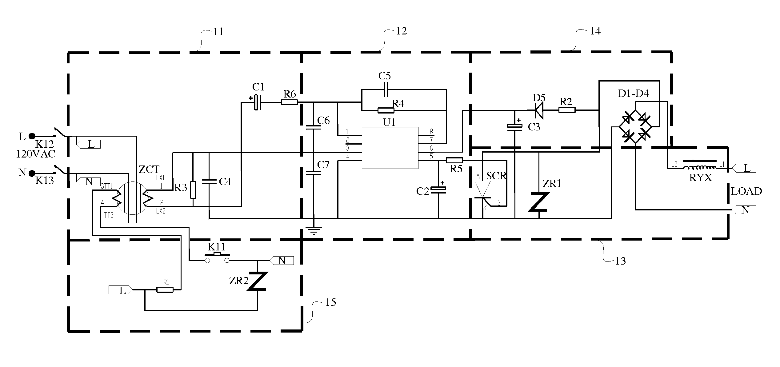
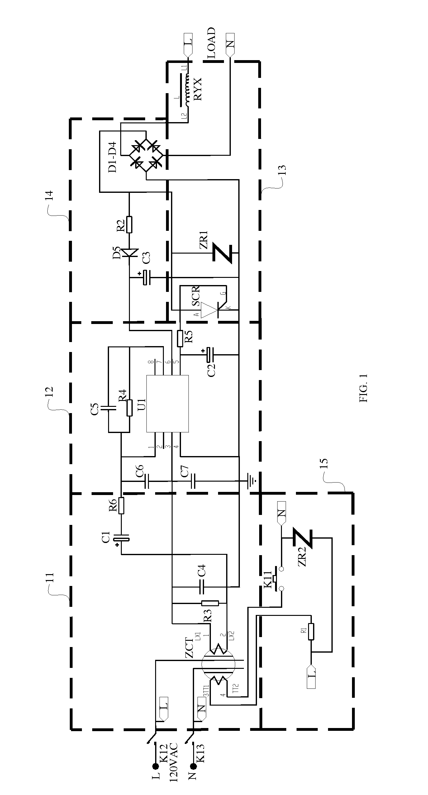
[0030]Referring to FIG. 1, which is a schematic view of a safe quick disconnect leakage protector in accordance with the present disclosure, the leakage protector includes a power supply circuit 14, a sampling circuit 11, a main control circuit 12, a couple of single-pole single-throw switches K12, K13, an on and off control circuit 13, and a testing circuit 15, wherein:

[0031]the power supply circuit 14 is configured for supplying power to the leakage protector;

[0032]the sampling circuit 11 is connected between a live wire L and a neutral wire N of an external power supply for collecting a leakage current signal between the live wire L and the neutral wire N and outputting the leakage current signal;

[0033]the main control circuit 12 is configured for receiving the leakage current signal outputted from the sampling circuit 11, amplifying the leakage current signal, and outputting a grounding failure control signal;

[0034]one of the couple of single-pole single-throw switches K12, K13 ...
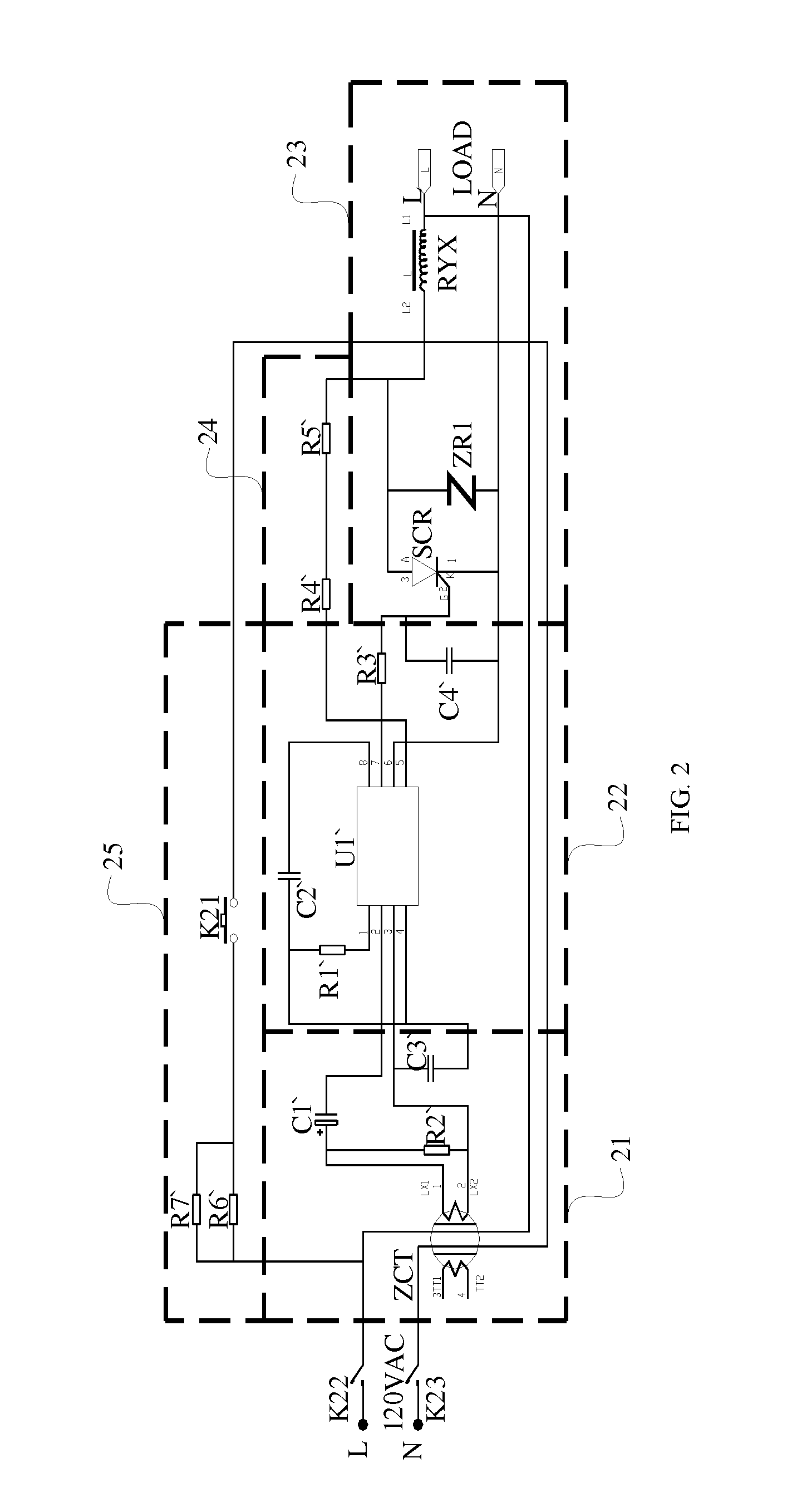
second embodiment

[0071]Through the above comparison, it can be concluded that function modules of the two leakage protectors of the two embodiments are identical to each other, and each leakage protector includes the sampling circuit, the main control circuit, the on and off control circuit, the power supply circuit, the testing circuit, and the couple of single-pole single-throw switches. Due to the fact that the chips adapted in the two embodiments are different from each other, the structure of the leakage protector of the second embodiment is much simpler.

[0072]As discussed above, the leakage protector of the present disclosure is powered by the power supply circuit; the sampling circuit collects the leakage current signal between the live wire and the neutral wire and outputting the leakage current signal; the main control circuit receives the leakage current signal outputted from the sampling circuit, amplifies the leakage current signal, and outputs a grounding failure control signal when the...


PUM


Abstract

The present disclosure provides a safe quick disconnect leakage protector, including a power supply circuit, a sampling circuit, a couple of single-pole single-throws, an on and off control circuit, and a testing circuit. The sampling circuit collects the leakage current signal between the live wire and the neutral wire and outputting the leakage current signal; the main control circuit receives the leakage current signal outputted from the sampling circuit, amplifies the leakage current signal, and outputs a grounding failure control signal when the leakage current reaches the predetermined value; the on and off control circuit receives the grounding failure control signal outputted from the main control circuit and controls the single-pole single-throw switches to disconnect the load from the external power supply according to the grounding failure control signal, thereby protecting the load and improves the safety of the leakage protection of an electrical appliance.

Description

BACKGROUND[0001]1. Technical Field[0002]The present disclosure generally relates to electrical appliances, and more particularly, to a safe quick disconnect leakage protector.[0003]2. Description of Related Art[0004]In daily life, short circuits between electrified conductors in an electrical circuit of an electrical product, such as the short circuit between a neutral wire and a live wire, ground, a housing of an electrical equipment, and various kinds of grounded metal tube, etc, or an insulation resistance of the conductor relative to ground being smaller than a preset value, may cause a grounding failure, which may result in an over current and further a fire or an electrical shock. In order to avoid the situation, a leakage protection plug is widely applied to avoid the grounding failure.[0005]The leakage protection plug is arranged between a power supply and a load for determining whether there is a leakage in the electrical product by detecting an electrical potential differe...

Claims


Application Information

Patent Timeline
IPC IPC(8): H02H3/16
CPCH02H3/162H02H1/066H02H3/05H02H3/16H02H3/334H02H5/105
Inventor WANG, ZHONGYU
Owner SHENZHEN LONGWAY TECH
Why Eureka
Try Eureka