Supercharge Your Innovation With Domain-Expert AI Agents!

Fuel Cell System Comprising a Water Separator

a fuel cell and water separator technology, applied in the field of fuel cell systems, can solve the problems of affecting the overall performance affecting the functionality of the fuel cell, and liquid water not being able to pass into the cathode chamber region, so as to reduce the amount of catalyst material, prevent hydrogen emissions, and simple system design

Inactive Publication Date: 2014-06-26
DAIMLER AG
View PDF1 Cites 5 Cited by
  • Summary
  • Abstract
  • Description
  • Claims
  • Application Information

AI Technical Summary

Benefits of technology

This patent is about a new fuel cell system that reduces the amount of catalyst material needed and minimizes functional impairments. It includes a recirculation device and a water separator to prevent liquid water from entering the fuel cell system. The system also has a partial air flow that flows through the water separator and prevents hydrogen emissions. Overall, this design improves the efficiency and lifespan of the fuel cell system.

Problems solved by technology

The problem with the simultaneous discharge of water and gas arises when the discharge occurs in the cathode chamber of the fuel cell, which is indicated in the cited WO publication as optional.
On the other hand, however, the water, which is likewise discharged from the region of the recirculation device, may result in impairment of the functionality of the fuel cells.
Tests have shown that this introduction of water may impair the efficiency of individual fuel cells, thus adversely affecting the overall performance of the fuel cell.
This water separator is used to separate the water conveyed from the mixture through the discharge line and otherwise discharge it from the fuel cell system, so that liquid water is not able to pass into the region of the cathode chamber.

Method used


Image

  • Fuel Cell System Comprising a Water Separator
  • Fuel Cell System Comprising a Water Separator
  • Fuel Cell System Comprising a Water Separator

Examples


Embodiment Construction

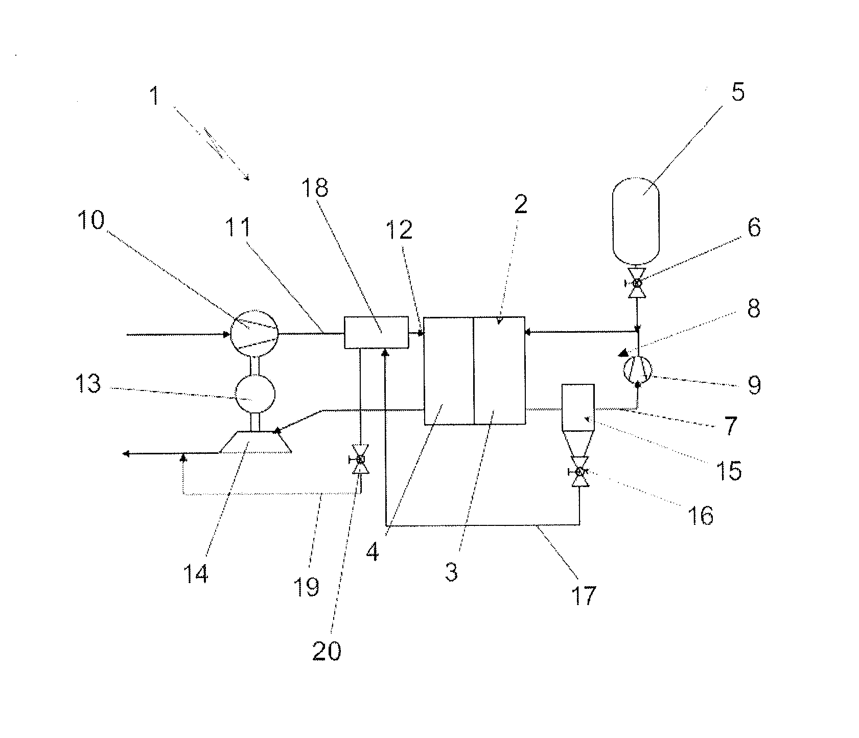
[0016]FIG. 1 illustrates, in a highly schematic manner, a fuel cell system 1 according to the present invention. The most important component of the fuel cell system 1 is a fuel cell 2, which is typically designed as a stack of individual fuel cells as a so-called fuel cell stack. The fuel cell 2 has an anode chamber 3 and a cathode chamber 4, which in the exemplary embodiments illustrated here are designed to be separated from one another by a proton-conducting membrane (PEM) in each case. The fuel cell 2 is thus a so-called PEM fuel cell stack.

[0017]The anode chamber 3 of the fuel cell 2 is supplied from a hydrogen store unit 5 via a metering valve 6 as well as a line element containing hydrogen from the hydrogen store unit 5. In the region of the anode chamber 3, unreacted hydrogen passes via a recirculation line 7 of a recirculation device 8 back into the area in which the fresh hydrogen flows to the anode chamber 3 via the metering valve 6. Thus, in a manner known per se, the r...


PUM

PropertyMeasurementUnit
areaaaaaaaaaaa
volume flowaaaaaaaaaa
forceaaaaaaaaaa

Abstract

A fuel cell system includes a fuel cell with an anode chamber and a cathode chamber. The fuel cell system also includes a recirculation device that recirculates anode exhaust gas to the anode input, which includes a discharge line for discharging liquid and / or gas from the region of the recirculation device, and an air conveying device for supplying the cathode chamber with a supply air flow. A water separator, which is connected to the discharge line and through which at least a portion of the supply air flow passes, is situated between the air conveying device and the cathode chamber in the area of the supply air flow.

Description

BACKGROUND AND SUMMARY OF THE INVENTION[0001]Exemplary embodiments of the invention relate to a fuel cell system having at least one fuel cell.[0002]German patent document DE 101 15 336 A1 discloses a fuel cell system having a recirculation device for recirculating the anode exhaust gas into the anode input. In these types of systems nitrogen and water become concentrated in the recirculated anode exhaust gas over time. For this reason, it is known from the general prior art and also described in the above-cited publication that valve units are situated in the area of the recirculation line which are occasionally opened in order to appropriately blow off the nitrogen from the region of the recirculation line and the region of the anode chamber. According to DE 101 15 336 A1, the “disposal” of this exhaust gas from the area of the anode loop may take place in various regions, which typically each have a catalytic surface or are in connection with a further component having such a cat...

Claims


Application Information

Patent Timeline
Patent Type & Authority Applications(United States)
IPC IPC(8): H01M8/04
CPCH01M8/04156H01M8/04111H01M8/04164H01M8/04231H01M8/04253Y02E60/50
Inventor BAUR, HOLGERPASERA, UWEPFLUGFELDER, HANS-JOERGSCHAUFLER, KARLSCHMALZRIEDT, SVENSTEINHUEBL, SIMONTEVES, HARALD
Owner DAIMLER AG
Features
  • R&D
  • Intellectual Property
  • Life Sciences
  • Materials
  • Tech Scout
  • Unparalleled Data Quality
  • Higher Quality Content
  • 60% Fewer Hallucinations
Learn More