Exhaust stack pipe cover

a stack pipe and exhaust system technology, applied in the direction of branching pipes, machine/engines, transportation and packaging, etc., can solve the problems of reducing engine performance and efficiency, generating false read-outs of sensors, and ingress of water, so as to reduce the backpressure in the exhaust system and effectively prevent water ingress

Active Publication Date: 2014-07-03
BLUE LEAF I P INC
View PDF8 Cites 7 Cited by
  • Summary
  • Abstract
  • Description
  • Claims
  • Application Information

AI Technical Summary

Benefits of technology

[0005]The present invention seeks therefore to provide a cover for the upper end of an exhaust stack pipe that effectively prevents ingress of water while minimising backpressure within the exhaust system.SUMMARY OF THE INVENTION
[0008]By virtue of its construction, the diverter serves to deflect the exhaust gases to flow smoothly out of the stack pipe into the annular space between the extension tube and the larger curved cover pipe to be discharged from the distal end of the cover pipe. The smooth flow avoids backpressure in the exhaust stack pipe while the cover pipe and the tapering deflector effectively prevent rain from entering the stack pipe.
[0011]It is also known to provide a flow restrictor within an exhaust stack to act as a venturi for creating a negative pressure in a pipe that draws air into the exhaust stack pipe from the engine intake air filter. Such an arrangement is used to help prolong the life of the intake air filter.
[0012]In an embodiment of the invention, drainage holes are formed in the exhaust stack pipe around such a flow restrictor. If water should condense on the section of the exhaust stack pipe downstream of the flow restrictor then such water can flow safely out of the drainage hole, the restrictor acting as a barrier to prevent the water from running down the inside surface of the exhaust stack towards a sensor.
[0014]Thus, in accordance with a second aspect of the invention, there is provided a cover for the upper end of an exhaust stack pipe comprising a curved cover pipe of greater diameter than the stack pipe having a proximal end to fit over the end of the stack pipe and a distal end from which exhaust gases are discharged, the cover pipe being shaped to prevent rain from falling directly onto the end of the stack pipe, and a flow diverter of lesser diameter than the cover pipe mounted within the proximal end of the cover pipe to overlie the end of the stack pipe, the flow diverter comprising an extension tube for mounting onto the end of the stack pipe having lateral openings and a tapering deflector extending into the extension tube to divert exhaust gases to flow into the cover pipe through the lateral openings in the extension tube.

Problems solved by technology

A problem that arises when an exhaust stack pipe is fitted with a sensor is that water ingress can damage the sensor caused for instance by the large temperature difference between the water and the sensor in working conditions.
Water ingress may further also generate a false read-out of a sensor.
However, such an obstruction in the path of the exhaust gases creates a backpressure within the exhaust system which reduces engine performance and efficiency.
Due to the reduced speed of the exhaust gases the temperature in these aftertreatment systems increase and components may be damaged permanently, resulting in high warranty and maintenance costs.

Method used


Image

  • Exhaust stack pipe cover
  • Exhaust stack pipe cover

Examples


Embodiment Construction

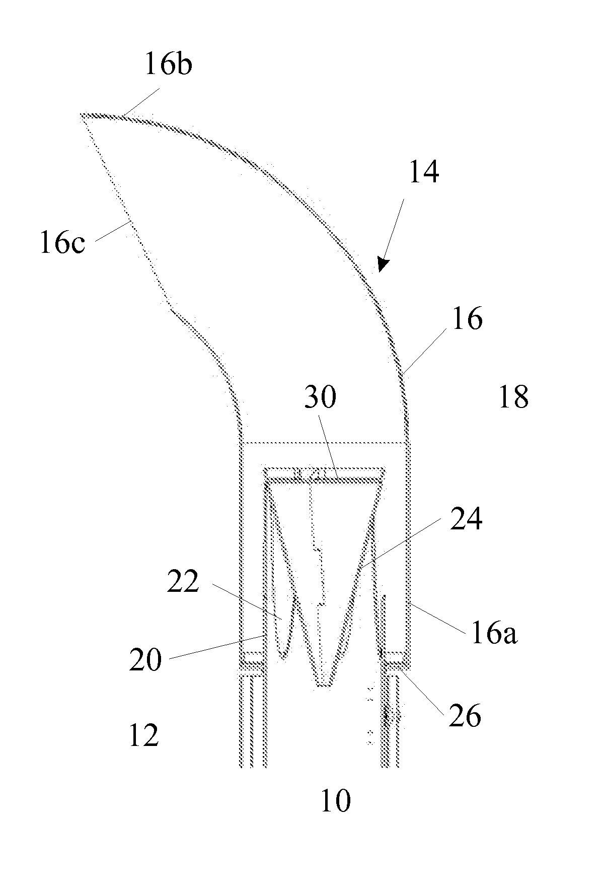
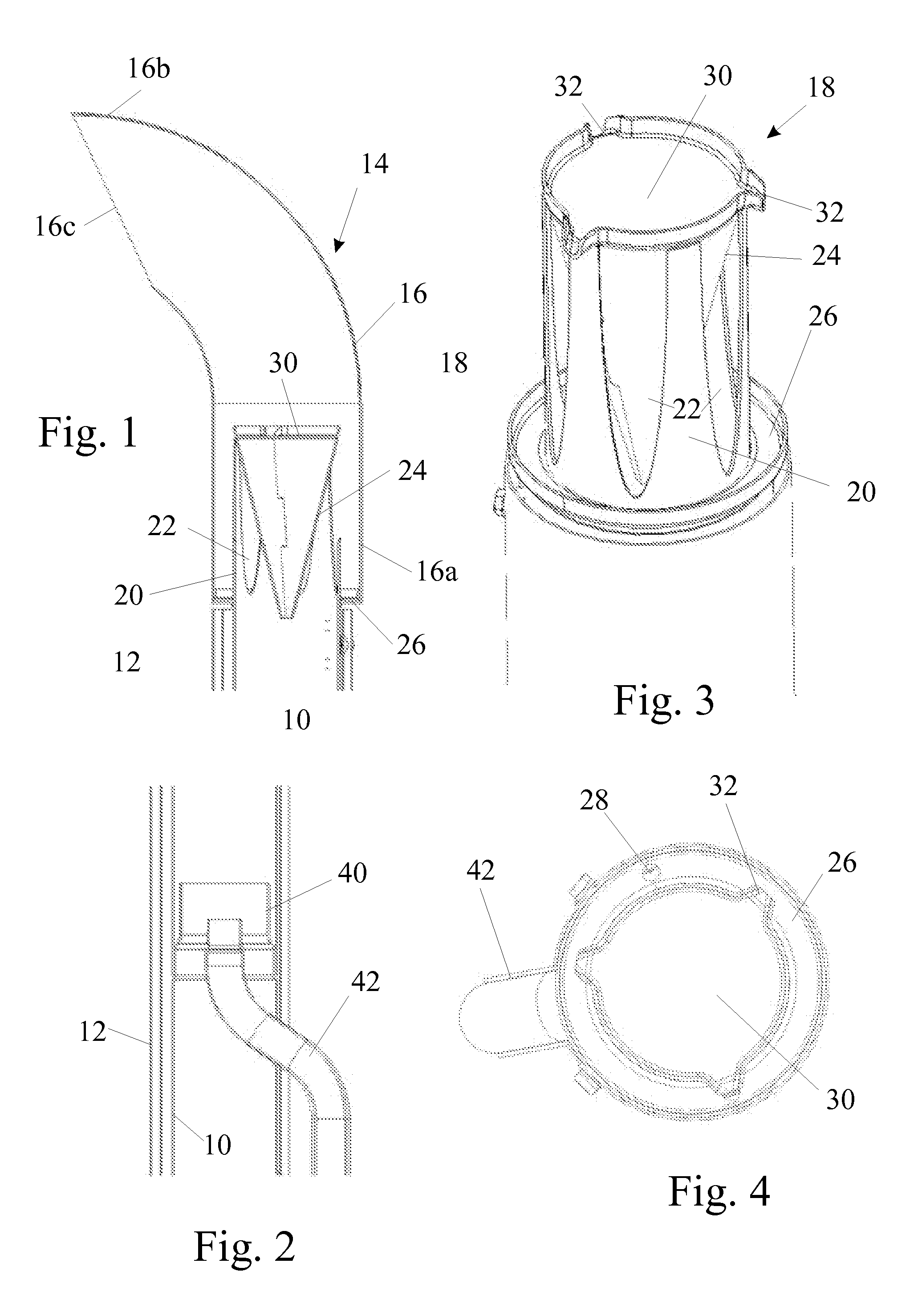
[0021]FIG. 1 shows a vertical exhaust stack pipe 10 surrounded by a heat shield 12 that surrounds the stack pipe over slightly less than its entire circumference and a cover, generally designated 14, fitted over the top of the stack pipe 10. The cover 14 comprises a curved pipe 16 having the same diameter as the heat shield 12 that bends through approximately 90° and has a proximal end 16a that is fitted over the stack pipe 10 and a distal end 16b with an undercut discharge opening 16c so that rain cannot drop vertically into the cover pipe 16.

[0022]A flow diverter 18 is disposed within the proximal end of the cover pipe 16. The flow diverter 18, which is shown more clearly in FIGS. 3 and 4, comprises an extension tube 20 of the same diameter as the stack pipe formed around it circumference with U-shaped or V-shaped cut-outs 22. In an alternative embodiment in which the cover 14 is integrated into the stack pipe, the tube 20 is constituted by the end of the stack pipe rather than by...


PUM


Abstract

A cover for the upper end of an exhaust stack pipe comprises a curved cover pipe of greater diameter than the stack pipe. The curved cover pipe has a proximal end to fit over the end of the stack pipe and a distal end from which exhaust gases are discharged. The cover pipe is shaped to prevent rain from falling directly onto the end of the stack pipe. A flow diverter of lesser diameter than the cover pipe is mounted within the proximal end of the cover pipe to overlie the end of the stack pipe. The flow diverter comprises an extension tube for mounting onto the end of the stack pipe having lateral openings and a tapering deflector extending into the extension tube to divert exhaust gases to flow into the cover pipe through the lateral openings in the extension tube.

Description

CROSS REFERENCE TO RELATED APPLICATIONS[0001]This application is the US National Stage filing of International Application Serial No. PCT / EP2012 / 054987, entitled “EXHAUST STACK PIPE COVER”, filed Mar. 21, 2012, which claims priority to Italian Application Serial No. TO2011A000256, filed Mar. 24, 2011, each of which is incorporated by reference herein in its entirety for all purposes.FIELD OF THE INVENTION[0002]The present invention relates to a cover for the upper end of an exhaust stack pipe to prevent ingress of water into the stack pipe.BACKGROUND OF THE INVENTION[0003]It is common for commercial and agricultural vehicles, such as tractors and harvesters, to use a vertical stack pipe for the engine exhaust. It is also known to provide sensors, such as NOx or lambda sensors, within vehicle exhaust pipes to monitor the contents of the exhaust gases, the output signals of such sensors being used by the engine management system. A problem that arises when an exhaust stack pipe is fit...

Claims


Application Information

Patent Timeline
Patent Type & Authority Applications(United States)
IPC IPC(8): F01N13/08
CPCY10T137/85938F01N13/082F01N2470/30F01N13/085F01N2470/00F01N2240/20F01N2590/08F01N13/08
Inventor WOLFCARIUS, NICODE MARCO, CARLO
Owner BLUE LEAF I P INC
Why Eureka
Try Eureka