Heat-Exchange Apparatus

Inactive Publication Date: 2014-07-03
OBSHCHESTVO S OGRANICHENNOJ OTVETSTVENNOSTJU PRORYVNYE INNOVATSIONNYE TEKHNOLOGII
View PDF15 Cites 12 Cited by
  • Summary
  • Abstract
  • Description
  • Claims
  • Application Information

AI Technical Summary

Benefits of technology

[0008]The device is intended to increase the area of contact of medium with the heat exchanging device, incre

Problems solved by technology

Disadvantage of this construction is the complexity of manufacture, as it consists of a large number of parts, as well as insufficient contact with the surface of heat exchanging device, which reduc

Method used


Image

  • Heat-Exchange Apparatus
  • Heat-Exchange Apparatus
  • Heat-Exchange Apparatus

Examples


Example

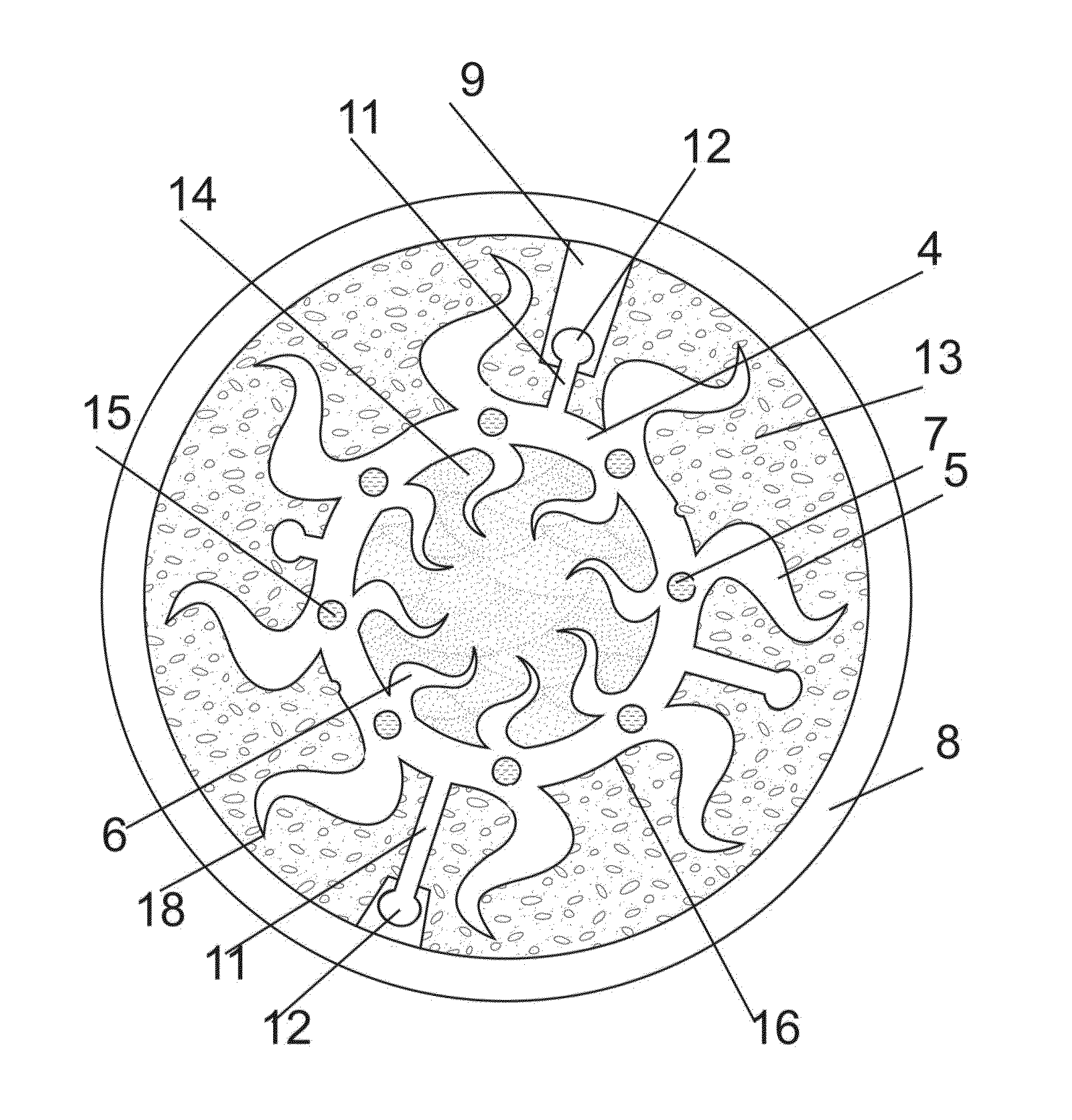
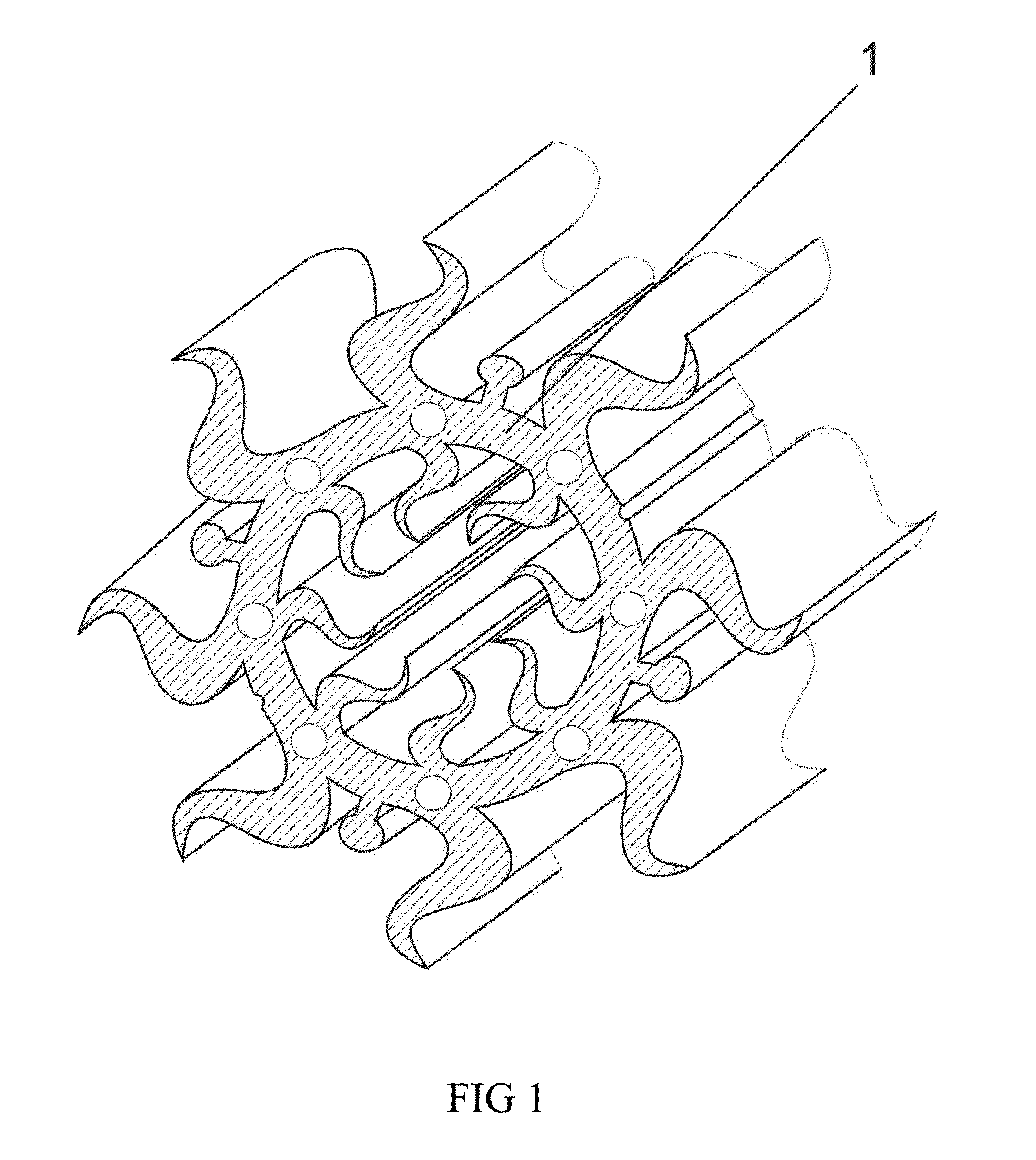
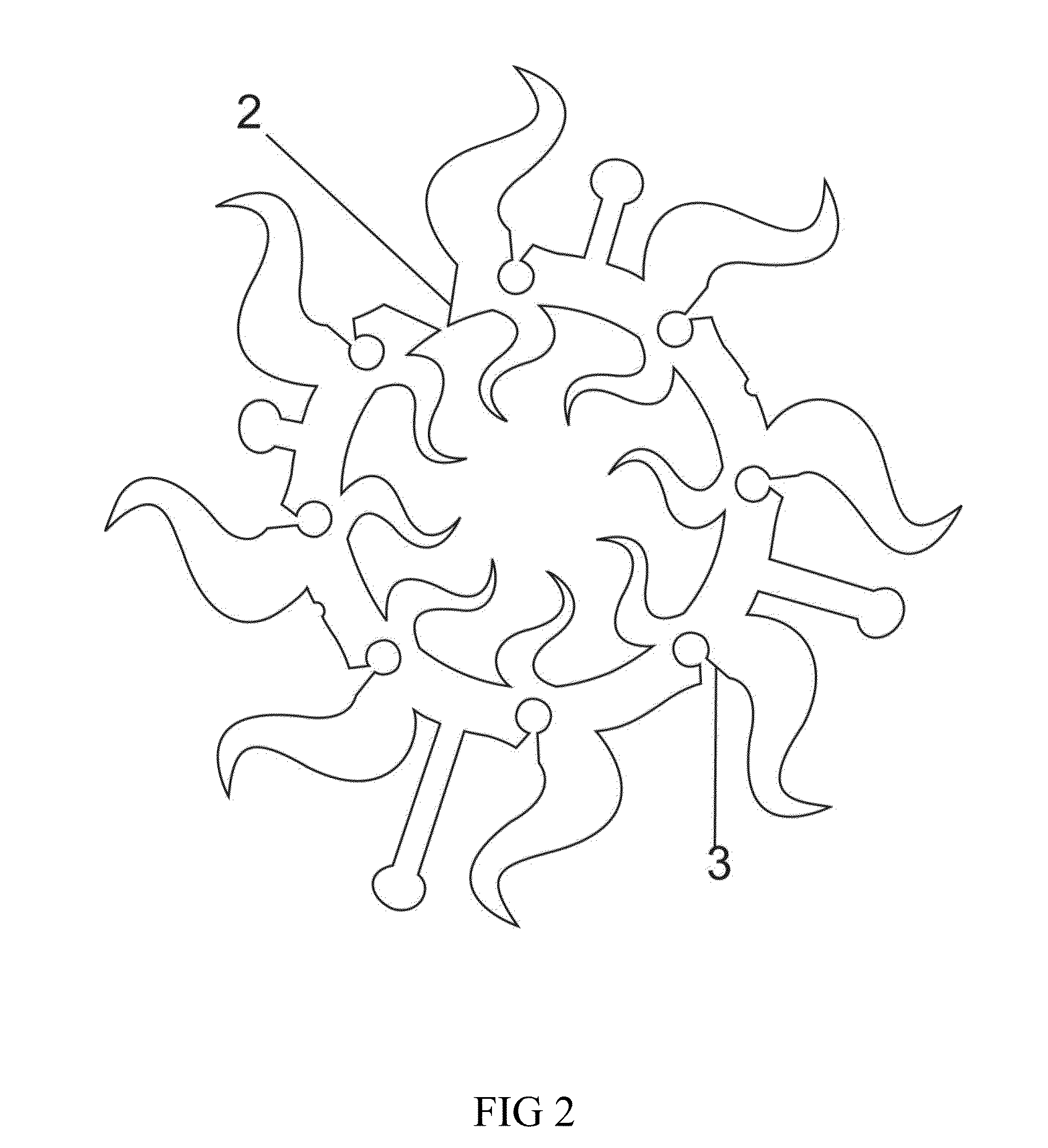
[0024]The heat exchanging device consists of one piece 1 (FIG. 1). It is made by extrusion. The device has technological gaps 2 and 3, which are subsequently welded (FIG. 2). The heat exchanging device is made as a tubular body 4 with the external 5 and internal 6 radial branches. The geometry of the radial external 5 and internal 6 branches is determined by calculation, depending of the thermal balance of the specified device. The tubular body in a circumferential direction has identical longitudinal round holes 7 (FIG. 3). The device is designed to be mounted inside the case 8 and is fixed inside the case 8 in the protruding parts 9 with apertures 10 by means of a fastener located on the external surface of the tubular body. The fastener is made in the form of projections 11 at the edges 12 (FIG. 4). The fastener can be of different length and is made in various places on the external surface of the tubular body (FIG. 11). The number of fasteners is chosen by calculation and depen...


PUM


Abstract

A heat exchanging device has a single extruded part made as a tubular body with external and internal radial branches. The tubular body has longitudinal round holes in a circumferential direction. At least one mount is on the outer surface of the tubular body. Internal and external radial branches taper from the base to the edge of branches and are made sinusoidal with a constant step and amplitude. They can be of the same width from the base to the edge of branches. The sinusoids of external radial branches can be of a variable amplitude and step from the base to the edge. The external radial sinusoidal branches can be of a different length relative and at different distances from each other. The radial branches can be have additional undulating projections. The round holes are made along the entire circumference of the body at equal distances from each other.

Description

RELATED APPLICATIONS[0001]This Application is a Continuation application of International Application PCT / RU2012 / 001122, filed on Dec. 27, 2012, which in turn claims priority to Russian Patent Applications No. RU2012105559, filed Feb. 17, 2012, both of which are incorporated herein by reference in their entirety.FIELD OF THE INVENTION[0002]The claimed heat exchanging device is a device that can be used for thermal and cool treatment of media, namely, liquids, gases, suspensions and slurries.BACKGROUND OF THE INVENTION[0003]It is known a multi-channel heat exchanging apparatus, comprising a package of at least three pipes arranged coaxially to form annular channels, two installed toward each other collector rings with outer coaxial stepped cylindrical surfaces, introduced into the channels and contacting with their walls, wherein each of the collectors has two longitudinal deaf channels communicated with the respective annular grooved channels (Patent of the Russian Federation No. 54...

Claims


Application Information

Patent Timeline
IPC IPC(8): F28F1/42
CPCF28F1/42F28F9/013F28D7/0066F28D7/1684F28F1/16F28F2275/143F28F1/422F28D7/10F28F2255/16F28F2275/14F28F2215/04
Inventor LEKHIN, VSEVOLOD P.
Owner OBSHCHESTVO S OGRANICHENNOJ OTVETSTVENNOSTJU PRORYVNYE INNOVATSIONNYE TEKHNOLOGII
Why Eureka
Try Eureka