Illumination Apparatuses

a technology of illumination apparatus and chromaticity, which is applied in the direction of lighting and heating apparatus, electrical apparatus, lighting heating/cooling arrangements, etc., can solve the problems of reduced service life, poor brightness and chromaticity of led bulbs, and the inability to meet all consumer demands. achieve the effect of high thermal and electrical conductivity

Inactive Publication Date: 2014-07-03
EVERGRAND HLDG
View PDF2 Cites 3 Cited by
  • Summary
  • Abstract
  • Description
  • Claims
  • Application Information

AI Technical Summary

Benefits of technology

[0018]According to still another aspect of the present invention, an illumination apparatus is provided. The illumination apparatus comprises: a body; a standard metallic lamp adaptor coupled to the body; a light source module comprising a heat pipe having high thermal and electrical conductivity, a substrate, a plurality of LED chips operatively mounted on the transparent substrate, a phosphor powder layer encapsulating the LED chips, and a pair of conductive wires electrically connected to the LED chips for transmitting electric power to the LED chips, wherein the heat pipe comprises a top portion mounted with the substrate and a bottom portion extending to the adaptor and electrically connected to the power supplying terminal of the adapter, and wherein one conductive wire in the pair of conductive wires is electrically connected to the heat pipe, and the other conductive wire in the pair of conductive wires is electrically connected to the ground terminal of the adaptor; and a transparent housing coupled to the body, so that the LED chips are enveloped within the transparent housing.

Problems solved by technology

However, the LED bulb now available in the market still cannot satisfy all the consumer's demands, as it can only provide light emission over 180 degree and has relatively poor brightness and chromaticity compared to the conventional incandescent bulb.
Moreover, the LED bulbs now available in the market normally demonstrate a poor heat dissipation capability, resulting in a reduced service life.

Method used


Image

  • Illumination Apparatuses
  • Illumination Apparatuses
  • Illumination Apparatuses

Examples


Embodiment Construction

[0043]Before the present invention is described in greater detail, it should be noted that the same or like elements are denoted by the same reference numerals throughout the disclosure. Moreover, the elements shown in the drawings are not illustrated in actual scale, but are expressly illustrated to explain in an intuitive manner the technical feature of the invention disclosed herein.

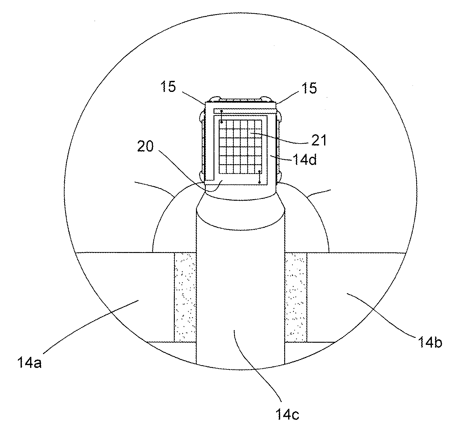
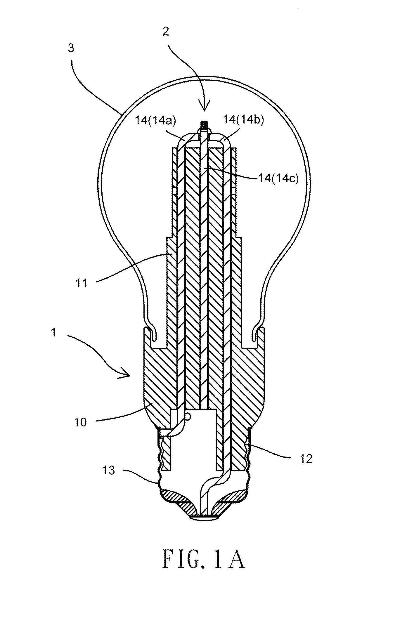
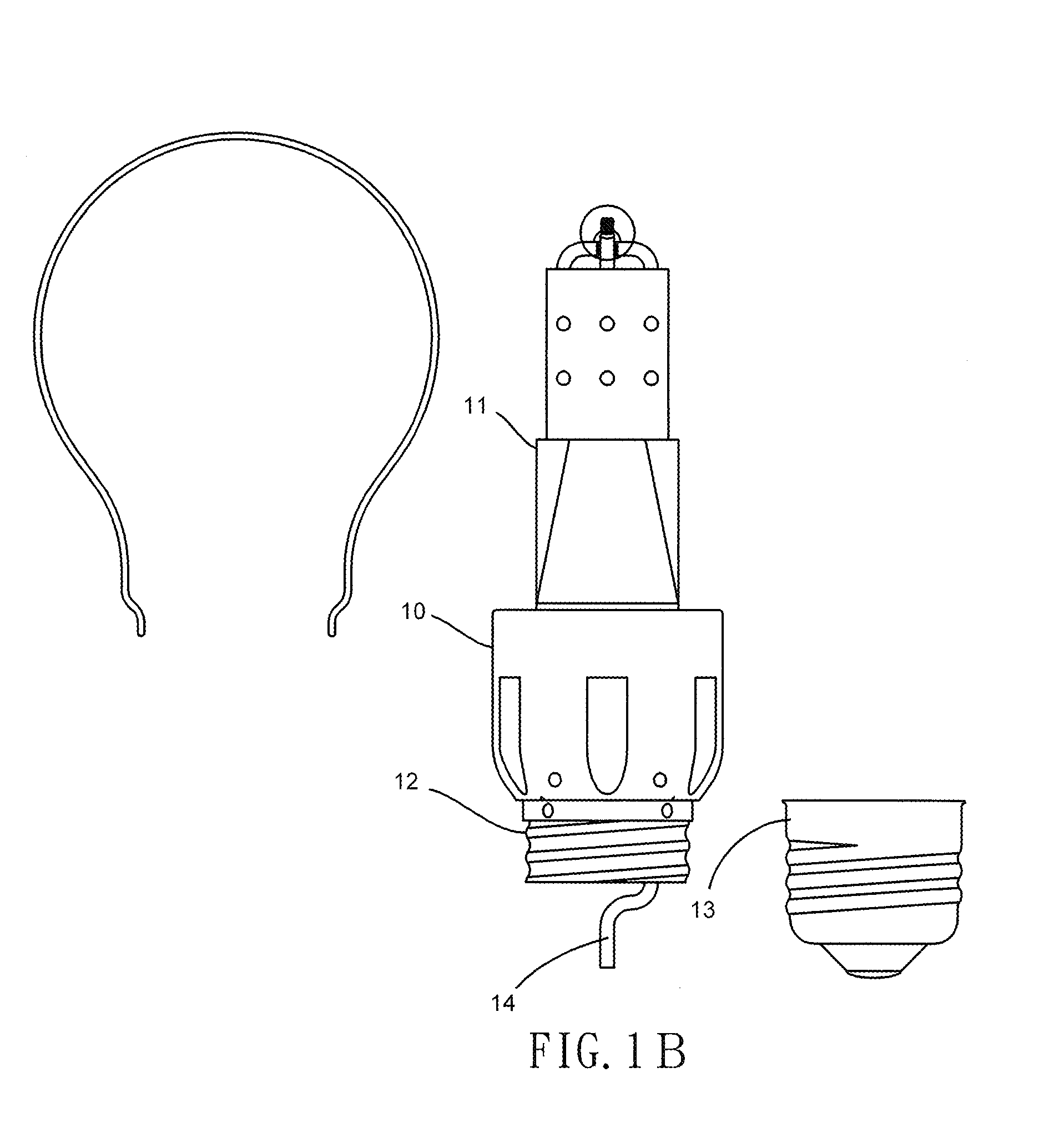
[0044]FIGS. 1A to 1C are schematic diagrams of the illumination apparatus according to the first preferred embodiment of the invention.

[0045]FIG. 1A is a partial schematic cross-sectional view of the illumination apparatus according to a first preferred embodiment of the invention. As shown in FIG. 1A, the illumination apparatus comprises a body 1, a light source module 2 and a transparent housing 3.

[0046]The body 1 is made of material with high heat dissipation capability. According to the embodiment disclosed herein, the body 1 is made of ceramic material. Alternatively, the body 1 can be made of an...


PUM


Abstract

The present invention provides an illumination apparatus. The illumination apparatus comprises a body having a lower portion coupled to a standard metallic lamp adaptor and an upper portion; a light source module comprising an LED array of LED chips connected in series, a phosphor powder layer encapsulating the LED chips, and a pair of conductive wires electrically connected to the LED chips for transmitting electric power to the LED chips; and a transparent housing coupled to the upper portion of the body, so that the LED chips are enveloped within the transparent housing.

Description

PRIORITY CLAIM[0001]This application claims priority to R.O.C. Patent Application No. 101149951 filed Dec. 25, 2012, the entirety of which is incorporated herein by reference.BACKGROUND OF THE INVENTION[0002]1. Field of the Invention[0003]The present invention relates to illumination apparatuses.[0004]2. Description of the Prior Art[0005]While the incandescent bulb used to be the main type of illumination apparatus available in the technical field of illumination applications, it has been gradually replaced by light-emitting diode (LED) light bulb, as the latter shows much higher energy-saving property and is much more friendly to the environment. However, the LED bulb now available in the market still cannot satisfy all the consumer's demands, as it can only provide light emission over 180 degree and has relatively poor brightness and chromaticity compared to the conventional incandescent bulb.[0006]Moreover, the LED bulbs now available in the market normally demonstrate a poor hea...

Claims


Application Information

Patent Timeline
Patent Type & Authority Applications(United States)
IPC IPC(8): H01L33/64
CPCH01L33/647F21V29/85H01L2224/48091H01L2224/16225H01L2224/48227H01L2224/49107H01L2224/14F21K9/232F21Y2115/10H01L2924/00014Y02B20/30F21V29/717
Inventor SHEN, YU-NUNG
Owner EVERGRAND HLDG
Why Eureka
Try Eureka